126
Hardware Installation—Installing the
IFC-1010/2020
For connection of initiating devices and modules in this system, refer to
Figure 59 through Figure 63. This application is not suitable for separate
transmission of sprinkler supervisory or trouble conditions. For additional
ratings, refer to Circuit/Device Ratings and Connections Technical
Bulletin (LIT-448160).
Note: During system programming, NFPA menu option 72B must be
chosen.
Braided Shield/Drain Wire
SLC Loop
Channel A off
Loop Interface
Board Number 1
To Next Device
on SLC
Alarm Polarity Shown!
P3
P2
P4
P5
P6
R27
TB3
1 2 3 4 5 6
MPS-24A
Common24 VDC
This M510CJ
must be programmed as:
Software Type GAS
Address: L1M97.
(Contacts shown
in energized
position.)
Do Not Break Tabs!
LIB-200
1
2
3
4
5
6
7
8
Earth Ground
Connect wires to
two red terminals
on box.
A77-716B
1
2
9
8
7
6
3
4
5
NO
COM
NC
Black Wire
Red Wire
MBT-1
alarmsys
White Wire
Brown Wire
Listed Power
Supervision Relay
Gamewell
Model M34-56
Local Energy
Municipal Box
+
Channel B-
Channel B+
Channel A-
Channel A+
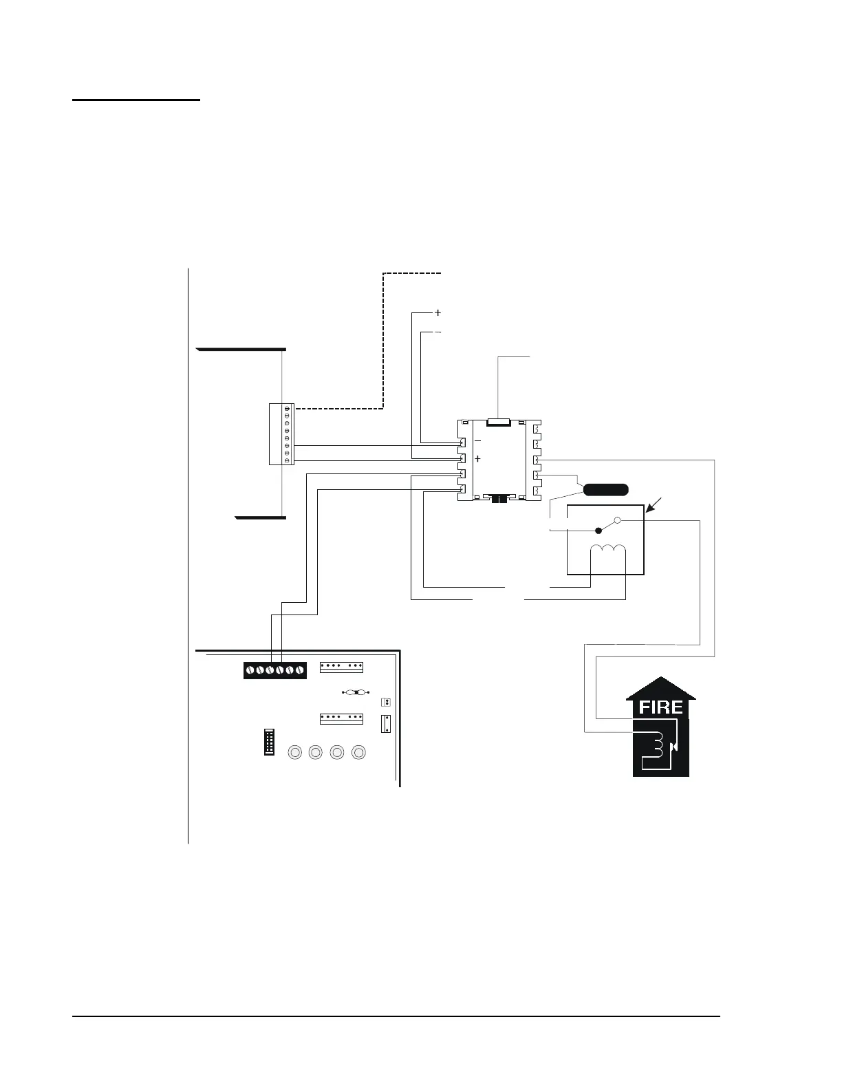
Figure 89: Auxiliary Fire Alarm System
Note: Wiring between the MBT-1 and the municipal box cannot exceed
1,000 meters (10,000 feet), must not cross any power lines, and
must not be in the vicinity of any high voltage.
NFPA 72-1999
Auxiliary Fire
Alarm Systems