Hardware Installation—Installing the IFC-1010/2020
133
Application and Clarification
Notes
The IFC-1010/2020 product is listed as a UL Multiple Listing, in
association with its original manufacturer. This allows Johnson Controls to
provide the latest products, upgrades, and updates available from the
manufacturer to the customer at the fastest rate and lowest cost. To
conform to this UL Multiple Listing process, this documentation must
closely reflect that which is distributed by the product’s original
manufacturer.
To supplement the UL Multiple Listed text given in this document, the
following table of descriptive Number Notes has been added.
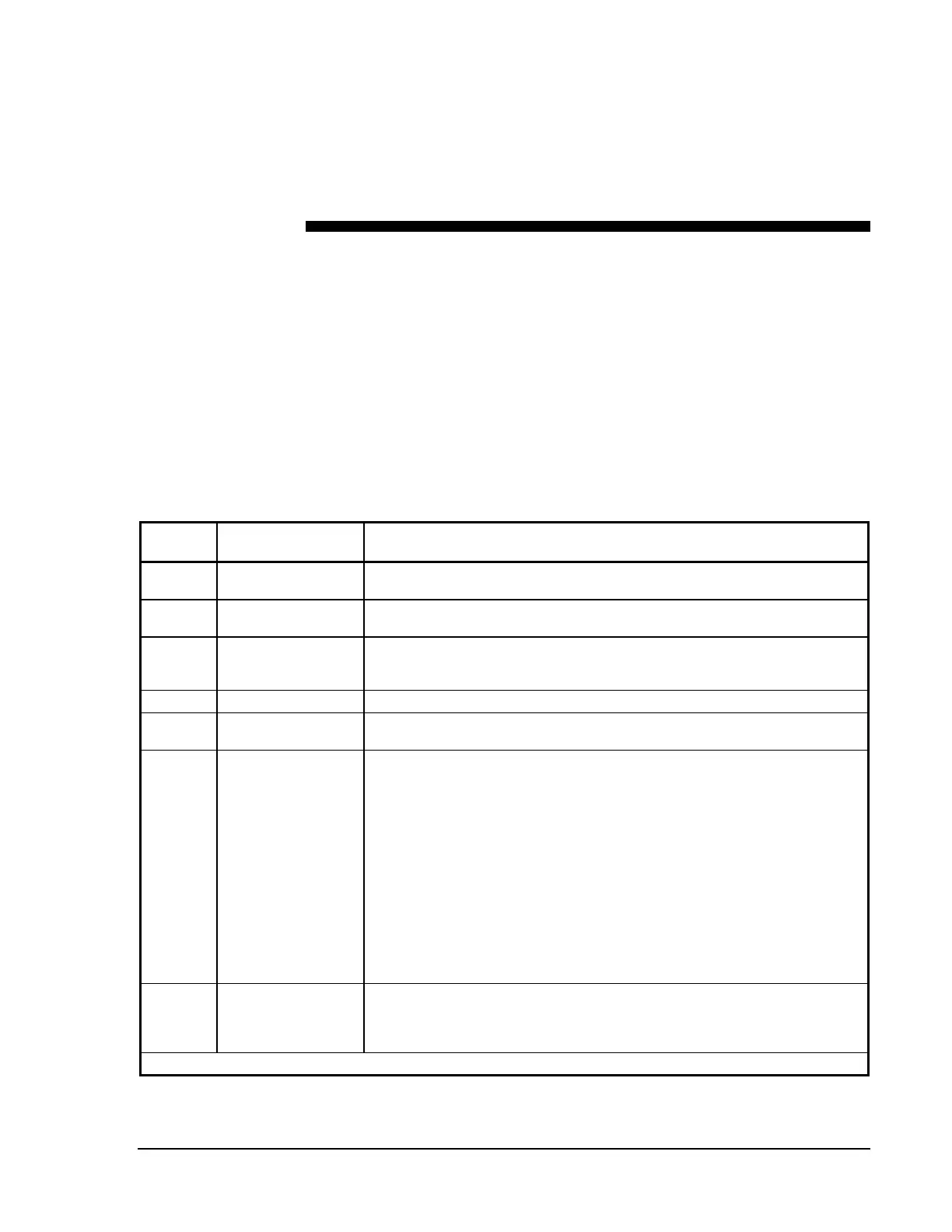
Table 13: Number Note Reference Table
Note
Number
Section Note
N1
Fire Alarm System
Limitations
This is a requirement of NFPA 72, the National Fire Alarm Code.
N2
Product Line
Information
The cabinets are identified by product codes CAB-A3 for the smallest
enclosure through CAB-D3 for the largest.
N3
BE-XP Transponder
Starter Complement
(Power-limited)
The XPP-1 also has one field-programmable addressable monitor point.
N4
Left Mount See the
Door Assembly Instructions
section in this document.
N5
Mounting the
Backbox
Do not allow any conduit entry at the bottom of the panel where the batteries
are to mounted (see Figure 2).
N6
CRT Function Keys The CRT keyboard may only be connected to the CRT that is located in the
same room as the IFC-1010/2020 control and may only remain connected
after system programming if the system is operated in accordance with
NFPA 72 Proprietary Fire Alarm System or as a Central Station Receiving
Unit. If the system firmware includes the modem programming option in
System Programming, there is a way to have the keyboard connected to the
CRT, even on Local Fire Alarm System configurations.
By entering Partial System Programming and selecting Additional System
Parameters (menu selection 9=PARM), you will find a prompt of
Change Modem Prog?
Selecting this and enabling the modem option at the
subsequent prompt disables the system function keys, plus the Ack/Step,
Programming, and Alter Status function keys on the CRT keyboard. With the
system function keys disabled, you can leave the keyboard connected to the
CRT and still be in compliance with the system’s UL Listing.
N7
LIB SLC Loop
Wiring
Requirements:
Operation
It is unnecessary to locate a M500XJ isolator module or B524BI
detector/isolator base as the first device on the SLC, since the LIB has
transorb and MOV protection.
Continued on next page . . .