64
Hardware Installation—Installing the
IFC-1010/2020
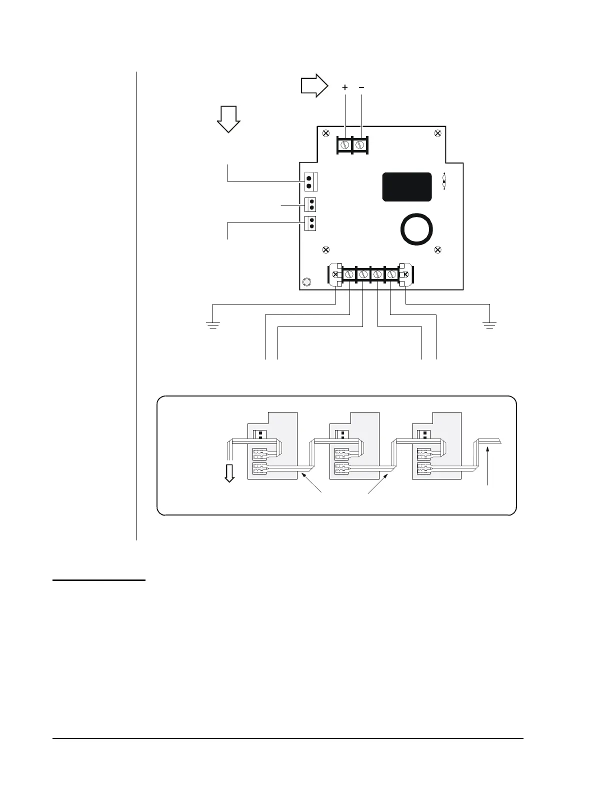
TB-2
P3
P1
P2
TB-1
Trouble
LED
(For Connections M5X0CJs)
Auxiliary Notification Appliance
Power Harness
(For Connection to XP Transponder)
Trouble Cable
Connect to P5 on the CPU
cable (Part Number 71033).
Earth Ground
Connect to AC
service ground.
Earth Ground
Connect to AC
service ground.
Connect to second
APS-6R (if present).
24 VDC Special Application Power
Unfiltered, unregulated, power-limited,
3.0 amperes maximum.
avpswire
First AVPS-24
P1
P2
Last Device in Chain
To CCM-1 (If employed)
To AMG-1 (If employed)
Cables 71033
For Multiple
Audio/Visual
Power Supplies
Connect to P5 on the CPU with
Cable 71033. Do not connect
to MPS-24A or MPS-24AE.
24 VDC Secondary Power
Connect to MPS-24A or MPS-24AE
TB2, Terminal 1 (+) and Terminal 2 (-).
Primary Power*
Connect to MPS-24A or MPS-24AE
TB1, Terminal 4 (Neutral) and Terminal 6 (Hot).
*Primary Power
APS-6R 120/240 VAC, 50/60 Hz, 150 watt
Figure 41: Optional AVPS-24 or AVPS-24E Field Wiring
The APS-6R Auxiliary Power Supply is designed to power devices that
require filtered, non-resettable power such as XP Transponder modules,
notification appliance circuit modules, and control modules. It provides
two 24 VDC (filtered) output circuits (3A each, 6A total, 4A continuous).
APS-6R
Auxiliary
Power Supply