Hardware Installation—Installing the IFC-1010/2020
131
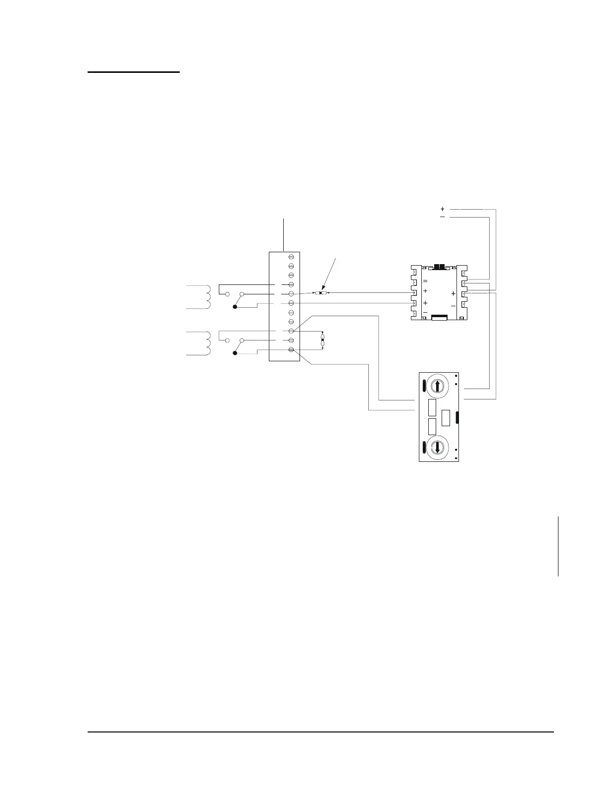
The application provided in Figure 92 is not suitable for separate
transmission of sprinkler supervisory signals. All circuits are supervised
and power limited. 18 AWG (0.75 mm
2
) is the minimum. There is a
maximum loop resistance of 40 ohms for the LIB-200. The maximum
distance between the Central Station/Receiving Unit and the M50xMJs is
10,000 feet at 12 AWG (3.25 mm
2
) for the LIB-200. For initiating device
connections, refer to Figure 65 and Figure 69.
Channel
ELR Model R-47K,
(N-ELR in Canada)
11
10
9
1
2
9
8
7
6
5
All circuits supervised and power-limited. 18 AWG minimum.
Maximum of 40 ohms SLC resistance. 10,000 feet at 12 AWG
maximum distance between the central station/receiving unit and
the M500MJ/M501MJs.
ELR Model R-47K,
(N-ELR in Canada)
Normally Closed
Trouble Contacts
Normally Open
Alarm Contacts
(Contacts shown in their normal state.)
LIB-200 in NFPA 71/72D receiving
unit IFC-1010/2020 SLC.
0
1
2
3
45
6
7
8
9
0
1
2
3
45
6
7
8
9
ADDRESS
LOOP
nfpapcsp
1
2
3
4
5
6
8
7
M500MJ
Programmed with
the software Type ID
MRTB.
M501MJ
Programmed with
the software Type ID
MON.
Figure 93: NFPA 72-1999 Proprietary and Central Station
Protected Premises Unit/Proprietary and Central Station
Receiving Unit Interface
Fire Alarm and
Trouble Signal
Transmission
 Loading...
