60
Hardware Installation—Installing the
IFC-1010/2020
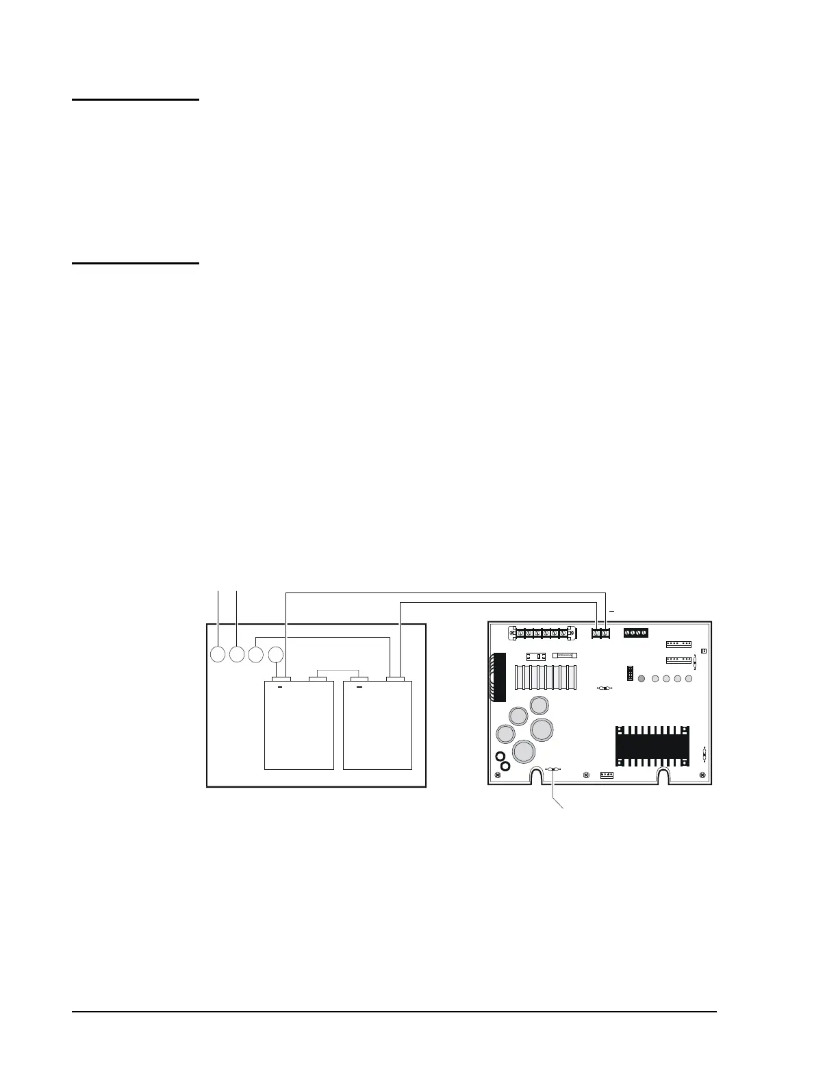
The Remote Battery Charger, NR45-24 is capable of charging
20-55 ampere-hour batteries.
N22
This unit is required if the
MPS-24A must deliver more than 3 amperes of current when no fire alarm
signal is present. The batteries and charger are housed in the
NR45-24 cabinet, which can be mounted up to 20 feet away from the
control panel. To determine the battery size needed in a particular system,
refer to Table 5.
With the breaker at the main power distribution panel turned off, connect
the primary Hot line to Terminal 1 on the NR45-24 and the primary
Neutral line to Terminal 2. All connections between the IFC-1010/2020
and the NR45-24 must be made in conduit, using 12 AWG wire. Do not
route AC wiring in the same conduit as other control panel circuits. Leave
the main power breaker off until installation of the entire system is
complete. Refer to Figure 38.
Do not connect AC power or batteries until the system is completely wired
and ready for testing.
4
_
3
+
21
+ +
NR45-24
or
NR45-24E
PS-12550
12 VDC 55-AH
Battery
PS-12550
12 VDC 55-AH
Battery
P3
P2
P4
P5
R27
JP5
P7
JP1
JP2
TB2
CB1 F1
1 2 3 41 2
TB1 TB3
1 2 3 4 5 6 7 8
N23
Cut JP1 to disable
on-board charger.
rembatt
24 VDC (supervised)
Maximum charge current for batteries is 2A (fast charge) or 20 mA
(trickle charge). Use 12 AWG wire in conduit (20 feet or less).
MPS-24A or
MPS-24AE
NR45-24
NR45-24E
120 VAC, 50/60 Hz
220/240 VAC, 50/60 Hz
Primary Power Source
Hot Neutral
+
Figure 38: Remote Battery Charger Connection
NR45-24
Remote Battery
Charger
Connecting the
Primary Power
Source
Connecting the
Secondary
Power Source