Hardware Installation—Installing the IFC-1010/2020
67
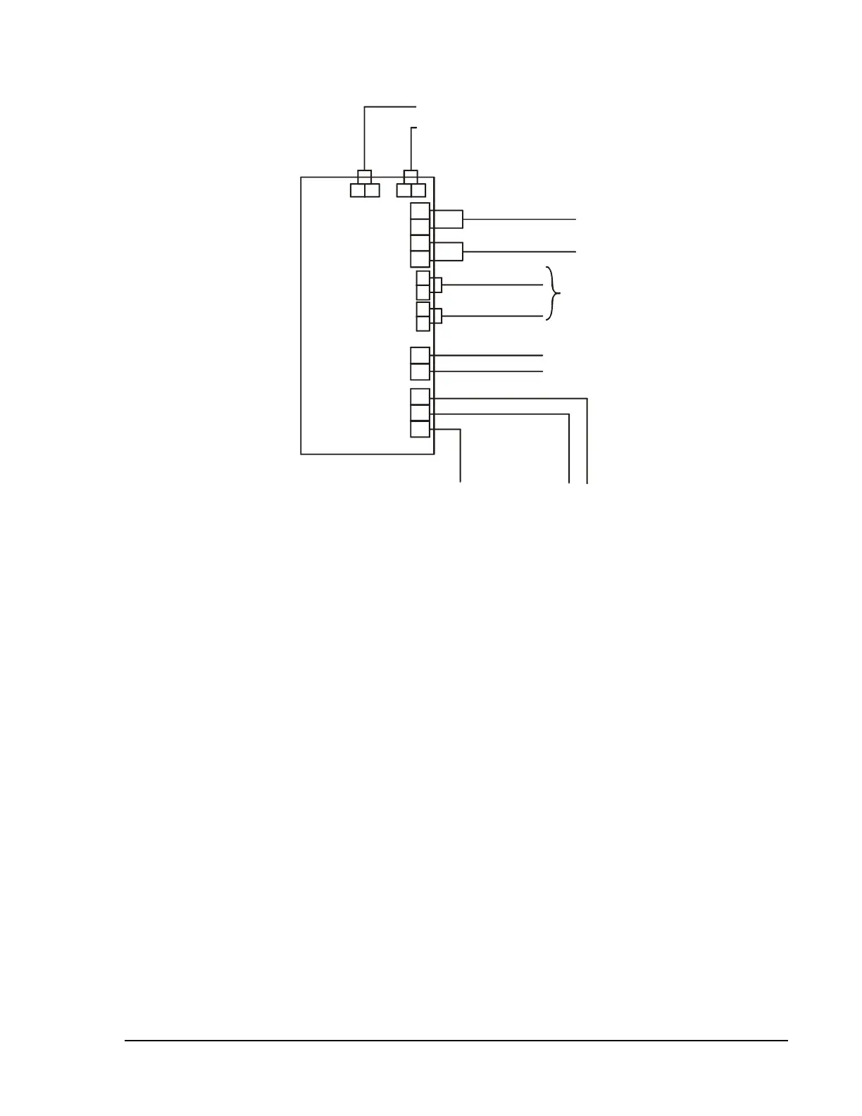
APS-6R
4321
APS-6R
J2 J1
TB2
J3
J4
TB3
TB1
+
+
-
-
Cable 71033
Cable 71033
Battery (+)
Battery (-)
Hot
Neu
Earth
Trouble Bus In/Out
Secondary Power
- 24 VDC batteries.
Connect to:
MPS-24A TB2-1 (+) and TB2-2 (-)
MPS-24B TB3-1 (+) and TB3-2 (-)
MPS-400 TB1-6 (+) and TB1-7 (-)
IFC-200 J3-1 (+) and 3-2 (-)
1122
Output Circuit 2 (24 VDC)
Output Circuit 1 (24 VDC)
Output Circuit 1: 3A @ 24 VDC (+10, -15%)
You can use J1 and J2 in place of TB2 when the
APS-6R is powering internal modules (such as, ICM-4,
ICE-A, TCM-2, TCM-4, UZC-256, IFC-200, XPC-8)
with compatible connectors.
Output Circuit 2: 3A @ 24 VDC (+10, -15%)
Earth Ground In
- Connection to
chassis or earth ground
terminal on main power supply
of next APS-6R.
Primary Power
- 120 VAC or 240 VAC.
Connect to:
MPS-24A TB1-5 (NEU) and TB1-7 (HOT)
MPS-24B TB1-3 (NEU) and TB1-4 (HOT)
MPS-400 TB1-2 (NEU) and TB1-4 (HOT)
IFC-200 TB7-3 (NEU) and TB7-1 (HOT)
11223
Figure 44: Typical APS-6R Wiring
Figure 45 shows typical trouble bus connections for multiple APS-6R
power supplies using trouble connectors J3 and J4.
Notes: 1. Use Cable 71033 or 75098 (same cables, different lengths) for
all wiring.
2. APS-6R J3 and J4 and AVPS-24 P1 and P2 can be
interchanged.
Connecting
Multiple APS-6R
Power Supplies