78
Hardware Installation—Installing the
IFC-1010/2020
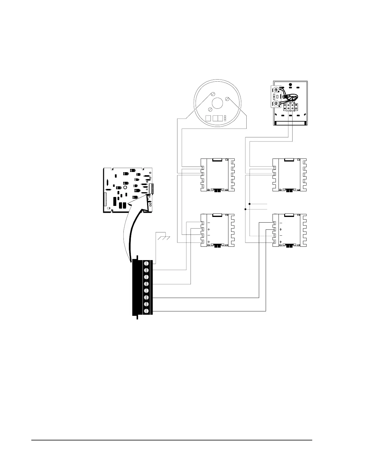
LIB Signaling Line Circuit (SLC) loops can be wired to meet the
requirements of an NFPA Style 4 (refer to Figure 51), Style 6
(refer to Figure 52), or Style 7 (refer to Figure 53) SLC.
8
7
6
5
4
3
2
1
2(+)
1(-)
3
LoopAddressType
IGN
Photo
Their
LIB-200
Separate T-tap to
other loop devices.
Connect to
chassis via
Cable 71073.
nfpastl4
Earth Ground
Channel B (-)
No Connection
Channel B (+)
No Connection
Channel A (-)
No Connection
Channel A (+)
Modules Modules
M500XJ
*N25
1
2
3
4
M500XJ
1
2
3
4
Detector Base Pull Stations
All terminals are power-limited.
ADDRESS
LOOP
0
1
2
3
45
6
7
8
90
1
2
3
45
6
7
8
9
Note: Refer to
and installation drawings supplied with each loop
device for rating and specification information.
Circuit/Device Ratings and Connections Technical Bulletin
(LIT-448160)
Figure 51: Typical NFPA Style 4 SLC Loops
N28