61Modul-AIR Exhaust Air Heat Pump Installation Guide
Modul-AIR Electrical Overview
All electrical wiring must be carried out by a competent installer and be installed in accordance with current
local Wiring Regulations.
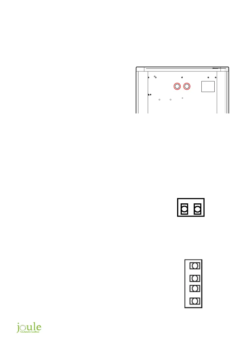
External Cable Entry
Tank Immersion Connection
DHW Tank Sensors
Power Supply Internal Connections
All external connections must be routed through the
entry points on the underside of the Modul-AIR unit,
these entry points are shown on the diagram to the
right.
Remove the front panel to access the electrical
enclosure. Cable entry to the enclosure is via an M25
cable gland. Ensure all cables are secured using
cable fixings.
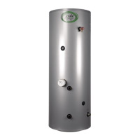
The Modul-AIR tanks immersion needs to be separately wired to
the internal PCB Board of the Modul-AIR unit during installation.
The immersion requires a 3 Core, 2.5mm2 power cable.
This cable is to be fed into the Modul-AIR unit using the entry
grommets. The Neutral (1) and Live (2) supply connections for the
immersion are on connecter block “P16” on the Modul-AIR PCB
board. The immersion must be grounded using the provided
earthing connections on the Modul-AIR casing.
Two Domestic Hot Water Tank Sensors are provided with the
unit. The sensors are 2m in length. The Sensor is to be installed
securely into the tanks aqua stat pockets, one for the Top pocket
the other for the Bottom pocket. The sensor cables are to be fed
into the Modul-AIR unit using the entry grommets. Connect the
probe cores to connector block “P6”. Top sensor cores to 5 & 6
and Bottom sensor cores to 3 & 4. There is no connection polarity
sensitivity. If required, the cables can be extended using a 2 core
0.5mm2 cable.
The Modul-AIR main PCB board was designed to take a 3 phase or Single-phase power feed. For ease of
installation in domestic applications the 3 Phase Mains Power board connection is prewired internally by
Joule to 3 no. 16Amp MCBs on a DIN rail. These are then connected in parallel to a single-phase Live rail
terminal. The Neutral and Earth for the board is also wired to terminals on said DIN rail. A 1 meter, 3 Core
4mm2 fly lead, fed through the unit’s cable gland, is supplied prewired to these terminals by Joule.
P6
6
5
4
3
1
(
N
)
2
(
L
)
P16