53
It will now be necessary to establish the maximum pitch value
required for your application prior to adjustment. For example, if you are
a beginning pilot, then your maximum negative pitch will be -5, and your
maximum positive pitch will be +10. The maximum pitch rage that you
will require will be +10. If you are a 3D pilot flying an Ergo 46 CCPM 3D,
then your maximum negative pitch will be -10, and your maximum
positive pitch will be +10 (+13 for autorotations). The maximum pitch
range that you will require will be +10 (or +13 for autos)
The maximum pitch range mentioned above must be established
through the use of the pitch travel value in the CCPM function. As
mentioned previously, do not try to establish the maximum pitch curve
values through adjustment of the Travel Adjustment Function, as this will
alter the pitch-to-aileron, and pitch-to-elevator travel values established in
Steps 7-5 and 7-6.
Please refer to the CCPM activation section, page 37-39, for
information on how to access the CCPM function.
Once the CCPM function has been activated, set the maximum
positive pitch settings as mentioned above. Since the CCPM function
does not allow for independent travel settings for positive and negative
pitch, it will be necessary to establish the maximum positive pitch, since
this is generally the largest degree of pitch in the pitch range. Once the
maximum positive pitch range is set, the maximum negative Pitch range
can be reduced as needed through the Pitch Curve Function.
Set the main rotor pitch gauge to the desired maximum pitch setting,
then increase or decrease the CCPM pitch travel (labeled Pitch or Ch6) as
needed until this pitch setting is achieved.
Once this procedure has been completed, the positive and negative
pitch settings for each flight mode can be adjusted through the radio’s
Pitch Curve Function. Please refer to your radio’s instruction manual for
more information.
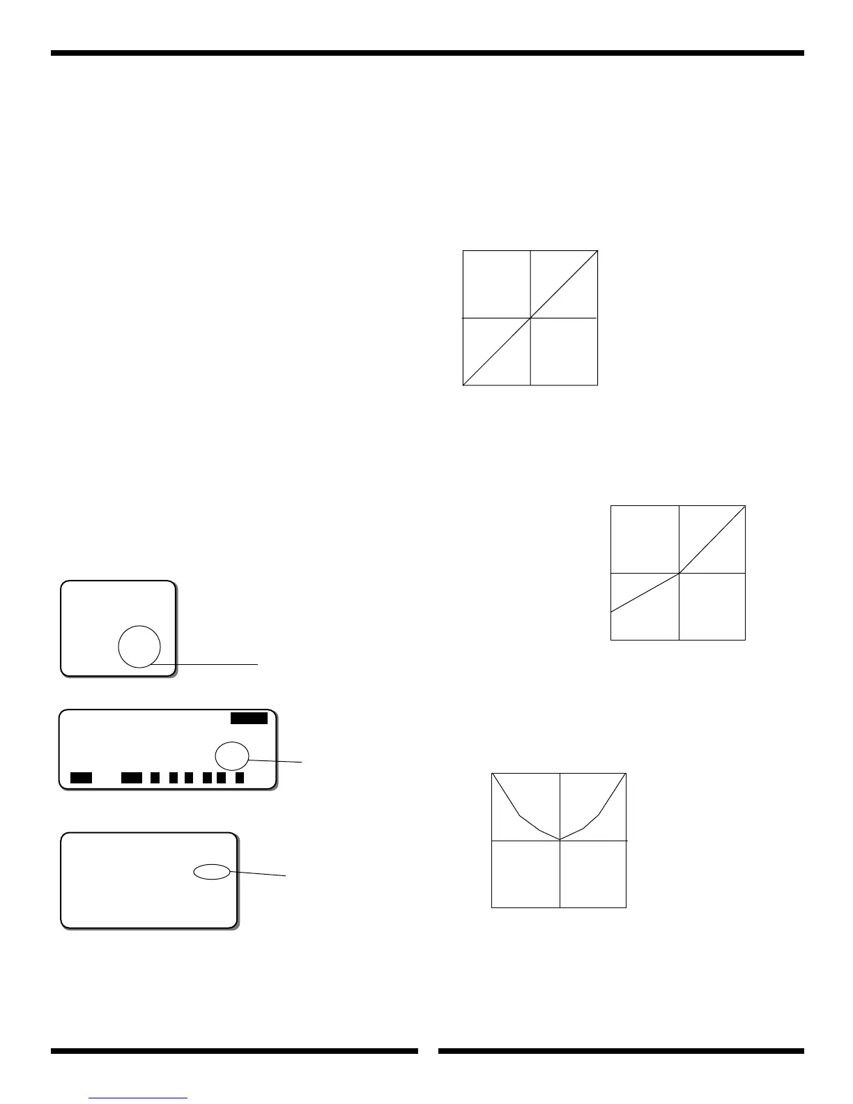
B. Throttle Curve Settings
Below are several examples of possible throttle curves during various
flight conditions. Since throttle curves can vary greatly due to engine
and muffler combinations, it will be necessary to fine tune and adjust
these values during test flights to achieve a constant main rotor rpm.
[SWASH
TYPE]
3SERVOS(120
•
)
EXP AILE ELEV PITCH
ENTER
SEL ACT + –
CL
+ –
CL
+ –
CL
Increase or decrease
the value as needed
Increase or decrease
the value as needed
Increase or decrease
the value as needed
[SWASH MIX]
3servos
120
•
XP8103
PCM 10 Series
XP652
AILE 60%
ELEV 60%
∞ PIT. -50%
mix CP6
——5500
100%
50%
40%
0% Idle
Power Output
Hovering (Linear Curve)
Stick Position
Low
Half
High
Flight Mode
N
100%
50%
0% Idle
Power Output
Stunt & Aerobatic Flight
Stick Position
Low
Half
High
Flight Mode
1
100%
100%
50%
0% Idle
3D Flight (Optional)
Stick Position
Low
Half
High
Flight
Mode 2
Power Output