54
It will also be necessary to set the correct idle speed of the
engine when the Throttle Hold Function is activated.
This idle value is located within the Throttle Hold Function. This
will allow the engine to remain at idle when practicing autorotations.
6. Revolution Mixing
It will be necessary to adjust the revolution mixing to properly
compensate for the torque of the engine during all flight
conditions (except autorotation). Since there are many variables
that can alter the value of the revolution mixing (engine, blade
pitch, fuel, etc.), it will be necessary to fine tune this function
during test flights. The following values are shown only as a
starting point toward achieving proper compensation:
7. Gyro Gain Adjustment
It will be necessary to adjust the “gain” or compensation of the
gyro to create the correct amount of “holding power” necessary
for a solid neutral tail rotor. The intent of the gyro is to
compensate for abrupt movements, or wind direction changes,
working in conjunction with the Revolution Mixing Function.
For hovering, it is recommended that you start with the gyro gain
at approximately 80°, and continue to increase slightly until the tail of
the helicopter “hunts,” then reduce the value slightly.
This same adjustment will also be necessary to achieve proper
forward flight. Generally, the gyro gain for forward flight will be
approximately 10%–20% less than that of the established hover gain
due to aerodynamic forces present in forward flight.
If you’re using a dual rate gyro, adjust the gain so that you’re
using “higher” gain setting for hover and the “lower” gain setting for
forward flight.
It will also be necessary to confirm the direction the gyro
compensates when the body of the helicopter is rotated.
To do this, turn the radio system on and suspend the helicopter
by the main rotor head. Next, move the rudder stick to the right and
watch the direction that the tail rotor servo arm travels. Now while
watching the tail rotor servo arm, rotate the body of the helicopter
counterclockwise. The servo arm should move in the same direction
as when the rudder stick was moved to the left. If the arm moves in
the opposite direction, reverse the gyro and re-test.
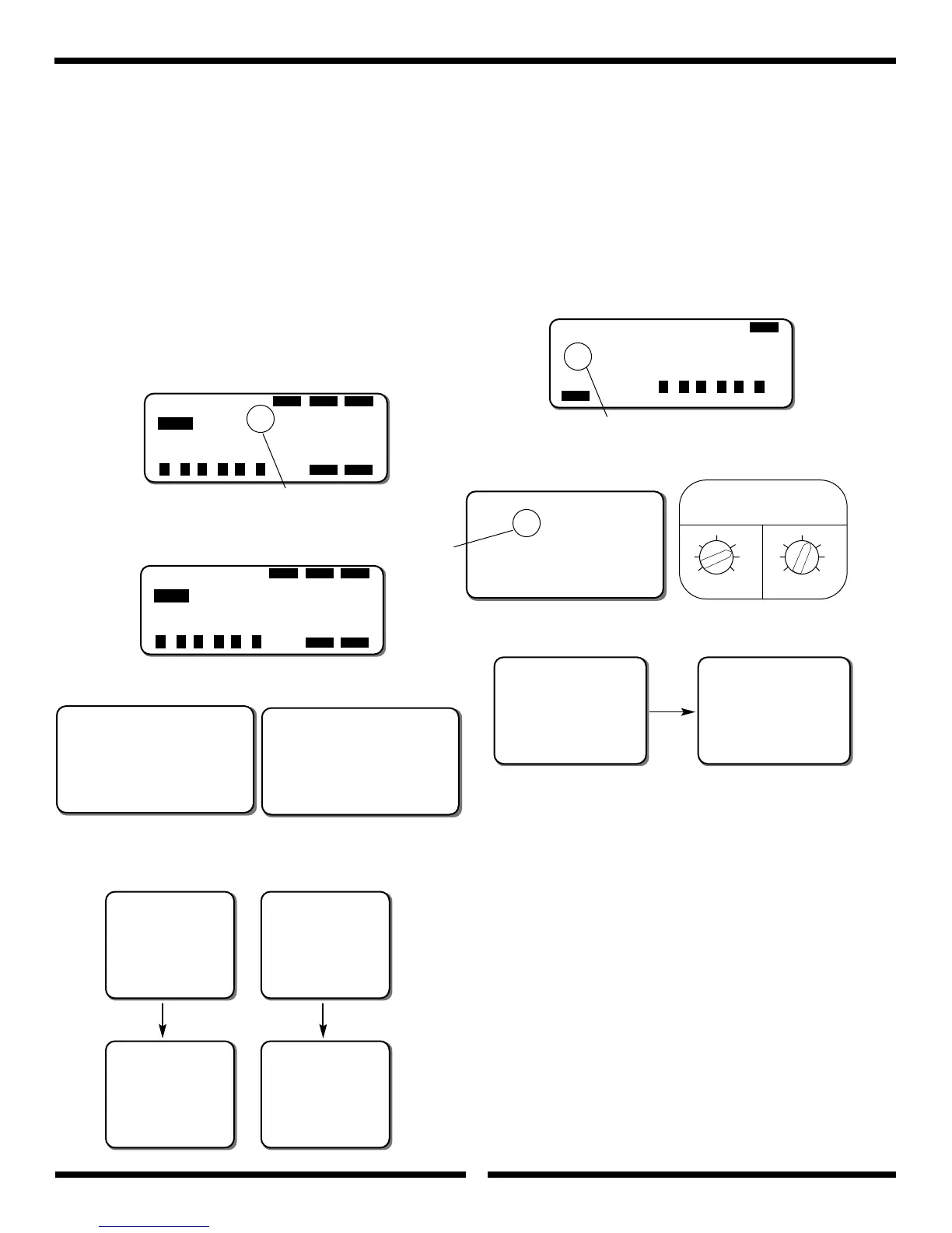
[ATS REVO-MIX]
DIR-RIGHT
-POS-
UP DN P HOV ZERO
10% 10% 0% 50 0
ENTERPAGE
STORE STORE
SEL
NORM
+ –
CL
+ –
CL
+ –
CL
Make certain that the compensation
direction is set to “Right.”
PCM 10 Series radio with NEJ450,
NEJ900 & NEJ3000 Gyros
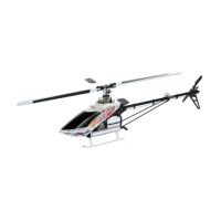
[GYROS SENS ADJ]
AUX3 0: 1: 2:
∞ 80% 60% 50%
ENTER
SEL
+ –
CL
+ –
CL
+ –
CL
Press SEL to select AUX3 or AUTO GAIN Function
Please refer to your radio’s instructions for more information.
Set gain controller values as shown.
PCM 10 Series radio with NEJ450,
NEJ900 & NEJ3000 Gyros
[ATS REVO-MIX]
DIR-RIGHT
-POS-
UP DN P HOV ZERO
35% 35% 0% 50 0
ENTERPAGE
STORE STORE
SEL
NORM
+ –
CL
+ –
CL
+ –
CL
PCM 10 Series radio with
NEJ120 & NEJ130 Gyros
[ATS. MIX]
REVO.Mix
NORM
∞Up R10%
DN R10%
STNT ACC.Mix
Up 0%
Dn 0% 0%
XP8103 with NEJ450, NEJ900 &
NEJ3000 Gyros
[ATS. MIX]
REVO.Mix
NORM
∞Up R35%
DN R35%
STNT ACC.Mix
Up 0%
Dn 0% 0%
XP8103 with NEJ120 & NEJ130 Gyros
mix RVV
++1100
mix RVD
++1100
XP652 with NEJ450,
NEJ900 & NEJ3000 Gyros
mix RVV
++3355
mix RVD
++3355
XP652 with NEJ120 &
NEJ130 Gyros
ger
trv. adj.
+80
%
XP652 with NEJ450,
NEJ900 & NEJ3000 Gyros
ger
trv. adj.
-60
%
XP652 with NEJ450,
NEJ900 & NEJ3000 Gyros
Channel Channel
Make sure that the direction is set to R (right)
[GYRO SENS]
RUDD D/R
£Rate:
∞0: 80%
1: 60%
XP8103 with NEJ450, NEJ900 &
NEJ3000 Gyros
JR GYRO
GAIN CONTROLLER
MIN MAX MIN MAX
01
0=80%
1=60%
Change
switch
Position
Set to Rudd
D/R Switch
(JR NEJ120 only)