Do you have a question about the JRC JMA-1030 Series and is the answer not in the manual?
Details safety measures to prevent electrocution from high voltage components and rescue procedures for victims.
Provides guidance on how to administer first aid to a person who has collapsed, minimizing risks.
Details procedures for performing CPR and cardiac massage when pulse and breathing have stopped.
Explains the step-by-step process of using an Automated External Defibrillator during CPR.
Explains the meaning of various safety symbols and pictorial indications used in the manual.
Outlines critical safety information, including DANGER, WARNING, and CAUTION statements.
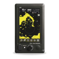
Lists all items included with the NCD-2256 display unit.
Lists items included with the NKE-2044 and NKE-1066 scanner units.
Illustrates the system configuration and identifies key components like scanners and display units.
Explains the importance of proper installation for radar performance and maintenance.
Covers selecting installation position, mounting options, dimensional drawings, examples, power cable, and signal connections.
Details selecting installation position, height, mounting, view angle, base confirmation, and clamping methods.
Instructions on connecting the radar's installation cable between the scanner and display units.
Overview of the control panel, buttons, rotary knob, and screen layout with explanations of their functions.
Instructions for safely powering the radar unit on and off, including preheating times and cautions.
Describes the different display modes available on the standby screen: Graphical, Normal, and Numerical.
Explains how to use the Man Overboard function to mark a position and facilitate rescue efforts.
Describes how to shift the display center to observe targets in a wider range.
Explains how to use the cursor to read target information, including bearing, range, and position.
Instructions on setting up guard zones to detect and alarm approaching targets or obstacles.
Guides on setting radar trail length and other trail display options for monitoring other ships' movement.
Details on how to use the Automatic Identification System (AIS) to display information about other vessels.
Explains the Target Tracking (TT) function for calculating and displaying target movement data.
Guides on selecting different operational modes (Standard, Coast, Float, River) for optimal radar performance.
Instructions on how to change the display color and brilliance based on ambient lighting conditions.
Explains how to assign frequently used functions to user option keys for quick access.
Details on drawing memos, lines, and symbols on the radar display for marking points of interest.
Information on adjusting various radar echo settings to optimize the radar image quality.
Guidance on adjusting the radar's tuning for optimal performance in both automatic and manual modes.
Explains how to switch between True and Relative motion display modes and bearing options.
Guides on setting the length of TT and AIS vectors to represent target speed and predict movement.
Details on using markers to set display options for EBLs, VRM, and Range Rings.
Instructions on configuring target tracking (TT) and AIS functions, including limits, display, and alarms.
Explains how to configure the NMEA information displayed in the upper right area of the screen.
Information on connecting an external monitor to the radar display unit using an optional kit.
Details about the NMEA cables required for connecting navigation equipment and their specifications.
Information on the rectifier unit used for power supply stabilization, especially when the ship's DC battery is insufficient.
Instructions on how to select and change the display language for the radar unit.
Guidance on adjusting the radar's tuning for optimal performance, especially when starting up.
Explains how to adjust the radar bearing to match the ship's compass for accurate target echo display.
Details on adjusting the radar range to ensure accurate indication of target distances, matching VRM data.
Instructions on setting the antenna height, which affects sea clutter rejection control.
Information on adjusting the noise level after installation, including fine-tuning recommendations.
Covers baud rate, RX port, TX port, TX data format, and target information transmission settings.
Guides on selecting input sources for heading, speed, and magnetic compass data.
Covers GPS status display, setting NMEA version, correction method, fix mode, and satellite configurations.
Covers settings that significantly impact the radar image, advising careful observation during changes.
Details on adjusting TT function settings like Vector Constant, Gate Size, and Gate Display for target tracking.
Covers PRF fine tuning, stagger trigger, antenna rotation speed, PRF mode, and timed TX functions.
Covers adjusting buzzer volume and calibrating the touch panel for optimal system control.
Guides on performing partial resets, clearing times, updating tables, and managing internal settings.
Covers setting system modes (Master/Slave/Demo), own ship outline, units, and range selection.
Details on setting own vector display, standby screen, numerical display, colors, waypoints, and AIS filters.
Instructions on masking error alarms to prevent display, with warnings about potential delays or missed alerts.
General guidelines for regular maintenance of the radar equipment, including cleaning.
Specific maintenance instructions for scanner (NKE-1066) and display (NCD-2256) units.
Outlines regular operational checks and performance tests for the radar equipment.
Information on parts requiring periodic replacement and safety precautions during replacement.
Lists and describes various alarm codes and their corresponding messages displayed by the system.
Provides guidance on identifying and resolving common issues like poor connections and circuit problems.
States the duration for which maintenance parts are kept after production discontinuation.
Provides guidance on troubleshooting, stopping operation, and contacting support for repairs.
A checklist to help identify and document radar failures before contacting service.
Advises following local laws and regulations for disposing of the radar unit.
Specific instructions for returning used magnetrons to the dealer or business office.
Provides detailed physical dimensions and mounting specifications for the NKE-1066 and NKE-2044 scanners.
Details the physical dimensions and mounting hole information for the NCD-2256 display unit.
Outlines the radar system's configuration, features, and models.
Provides comprehensive details on the radar's general specs, including emissions, display, environment, and power.
Lists detailed technical specifications for the NKE-1066 and NKE-2044 scanners.
Details the specifications for the integrated NCD-2256 display unit, including structure, dimensions, and functions.
Lists enabled input signals and possible output signals for navigation equipment.
Provides a wiring diagram showing the interconnection of components for the NKE-1066 scanner.
Provides a wiring diagram showing the interconnection of components for the NKE-2044 scanner.
Shows the interconnection diagram for the NCD-2256 display unit, detailing its various connections.
Illustrates the primary power supply circuitry and connections for the JMA-1030 radar system.
A comprehensive interconnection diagram showing how all major components of the JMA-1030 radar system are linked.
A quick reference guide summarizing common operations and icon functions for the radar display.
A detailed list of all functions accessible through the radar's main menu and their setting contents.
| Brand | JRC |
|---|---|
| Model | JMA-1030 Series |
| Category | Marine Radar |
| Language | English |