2-4
2
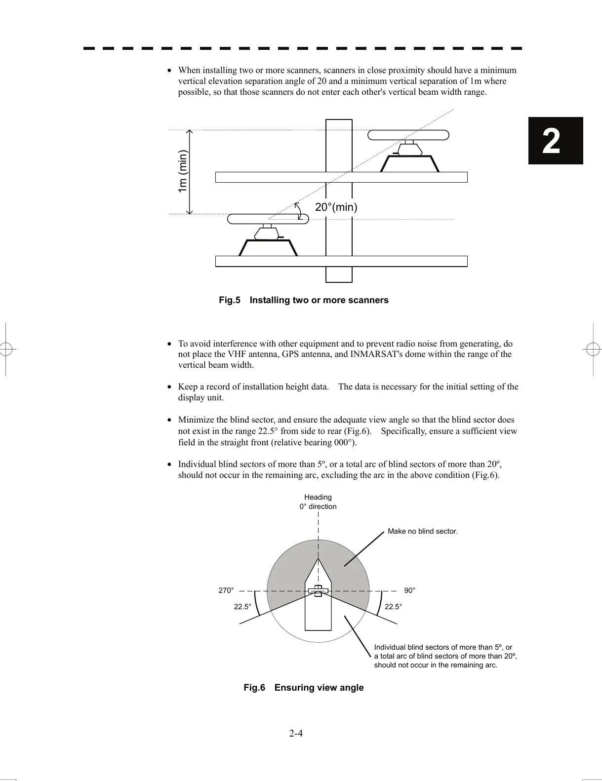
• When installing two or more scanners, scanners in close proximity should have a minimum
vertical elevation separation angle of 20 and a minimum vertical separation of 1m where
possible, so that those scanners do not enter each other's vertical beam width range.
1m (min)
20°(min)
Fig.5 Installing two or more scanners
• To avoid interference with other equipment and to prevent radio noise from generating, do
not place the VHF antenna, GPS antenna, and INMARSAT's dome within the range of the
vertical beam width.
• Keep a record of installation height data. The data is necessary for the initial setting of the
display unit.
• Minimize the blind sector, and ensure the adequate view angle so that the blind sector does
not exist in the range 22.5° from side to rear (Fig.6). Specifically, ensure a sufficient view
field in the straight front (relative bearing 000°).
• Individual blind sectors of more than 5º, or a total arc of blind sectors of more than 20º,
should not occur in the remaining arc, excluding the arc in the above condition (Fig.6).
Heading
0° direction
90°270°
22.5°
Make no blind sector.
Individual blind sectors of more than 5º, or
a total arc of blind sectors of more than 20º,
should not occur in the remaining arc.
22.5°
Fig.6 Ensuring view angle
 Loading...


