2-5
• For radar installations with two radar systems, where possible, the antennas should be placed
in such a way as to minimize the blind sectors.
• Magnetron which has strong magnetic force is included in the antenna. Install the antenna
at least 6 meters away from nautical instruments including magnetic compasses and
chronometers.
* If there is a concern that structural objects existing within the vertical beam width may
generate false images, equip the structural objects with a radio wave absorber. (There are
two types of absorbers: broadband type having no specific resonant frequency and
narrowband type which can absorb a band with a specific frequency. Use those where
applicable.) Furthermore, it is effective to install a metal reflector, which reflects radio
waves upwardly, between the antenna and a structural object so that the radar's radio wave
will not directly come in contact with the structural object.
When the structural objects exist in the surrounding area of Scanner unit, the false echo may
appear. The sector blank function is effective to reduce the signal reflection from the
structural objects. Because it can stop transmission. Therefore, it may reduce the false
echo appearance.
Note:
Because most radio wave absorbers have poor durability, some must be
replaced every year. When installing a reflector, the area to the rear of the
reflector becomes a blind sector. Therefore, minimize the size of the reflector.
When the sector blank function set to on, ensure a sufficient view field in the
straight front.
* The above procedures for selecting an antenna installation position are described based on
the radar's antenna. Comprehensively select the antenna position by considering other
antennas' installation procedure manual, hull's structure, strength of the selected position,
and vibration. About compass safe distance, refer to the instruction manual section 11.
3) Confirmation during test run
If the antenna vibrates a lot during test run, try to reduce or prevent vibration by reinforcing
the antenna mount base or using wire stays attached to the radar mast.
4) Others
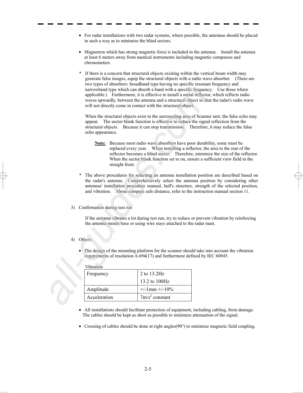
• The design of the mounting platform for the scanner should take into account the vibration
requirements of resolution A.694(17) and furthermore defined by IEC 60945.
Vibration
Frequency 2 to 13.2Hz
13.2 to 100Hz
Amplitude +/-1mm +/-10%
Acceleration 7m/s
2
constant
• All installations should facilitate protection of equipment, including cabling, from damage.
The cables should be kept as short as possible to minimize attenuation of the signal.
• Crossing of cables should be done at right angles(90°) to minimize magnetic field coupling.
 Loading...


