TB105 Set the voltage level of step gyro
1-2: Normal setting (factory default setting)
2-3: Gyro low voltage (CD56 lights at 22 Vdc or less. However, the gyro I/F circuit of the
JM
A-
5300MK2 operates on power supplied from the display unit even when the
display unit is turned off. Thus, there is no particular need to switch (although it
will still operate if it is switched).
<2> Connect the gyro signal and log signal ca
bles to t
he gyro I/F circuit (PC4201).
CMJ-304D/E side Connecting device side
TB10 Gyro signal (synchro/step)
TB20 Log signal (synchro/pulse)
3
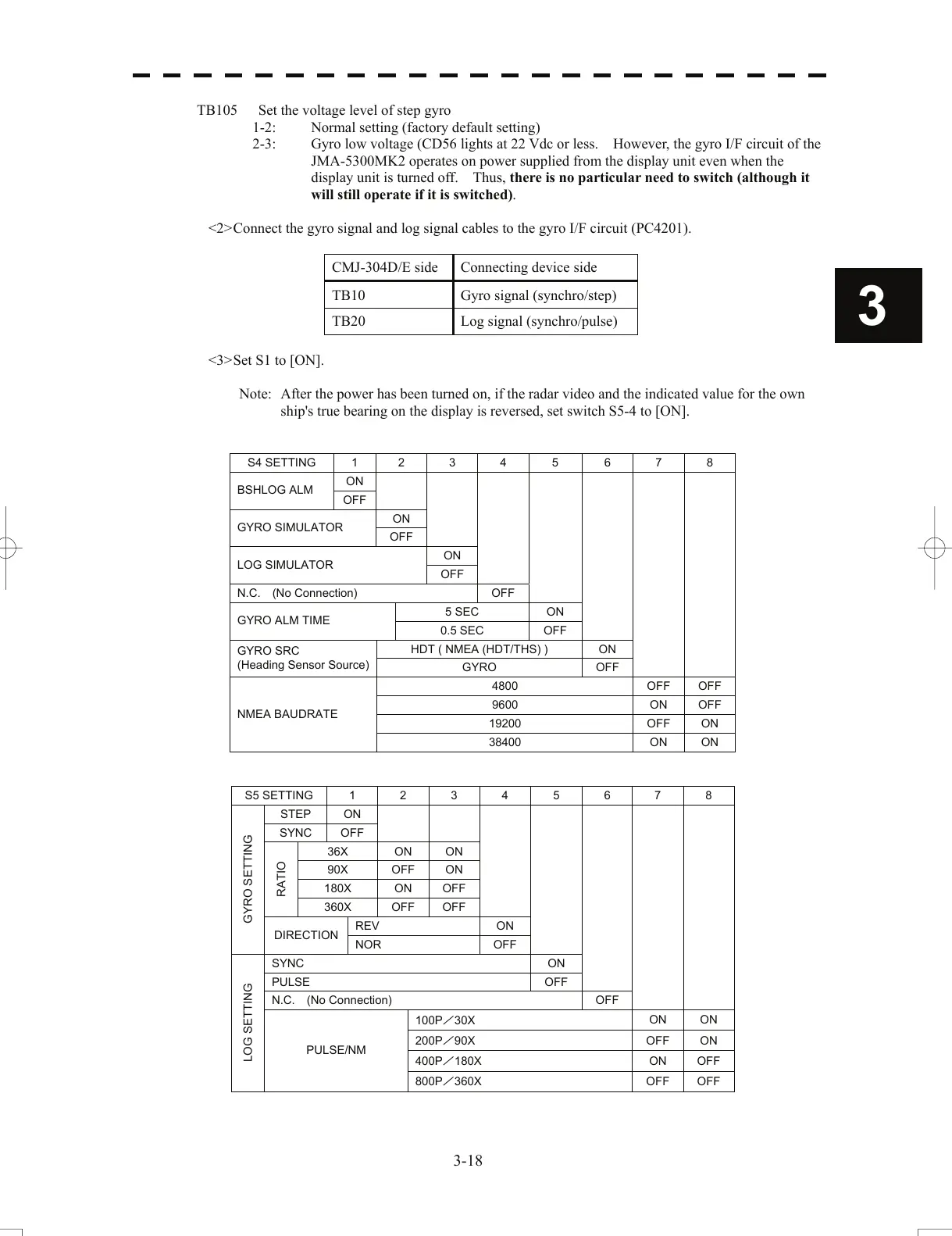
<3> Set S1 to [ON].
Note: After the power has been turned on, if the
ra
dar video and the indicated value for the own
ship's true bearing on the display is reversed, set switch S5-4 to [ON].
S4 SETTING 1 2 3 4 5 6 7 8
ON
BSHLOG ALM
OFF
ON
GYRO SIMULATOR
OFF
ON
LOG SIMULATOR
OFF
N.C. (No Connection) OFF
5 SEC ON
GYRO ALM TIME
0.5 SEC OFF
HDT ( NMEA (HDT/THS) ) ON
GYRO SRC
(Heading Sensor Source)
GYRO OFF
4800 OFF OFF
9600 ON OFF
19200 OFF ON
NMEA BAUDRATE
38400 ON ON
S5 SETTING 1 2 3 4 5 6 7 8
STEP ON
SYNC OFF
36X ON ON
90X OFF ON
180X ON OFF
RATIO
360X OFF OFF
REV ON
GYRO SETTING
DIRECTION
NOR OFF
SYNC ON
PULSE OFF
N.C. (No Connection) OFF
100P/30X
ON ON
200P/90X
OFF ON
400P/180X
ON OFF
LOG SETTING
PULSE/NM
800P/360X
OFF OFF
3-18
 Loading...


