EasyManuals Logo

JRC JMA-5312-6 Installation Manual

JRC JMA-5312-6
160 pages
To Next Page IconTo Next Page
To Previous Page IconTo Previous Page
Page #82 background imageLoading...
Page #82 background image
Untwist the core wires and straighten each wire.
After straightening, arrange the core wires so that the wires
are aligned in the wiring order.
NOTE: The picture shows the order of “Wiring A.”
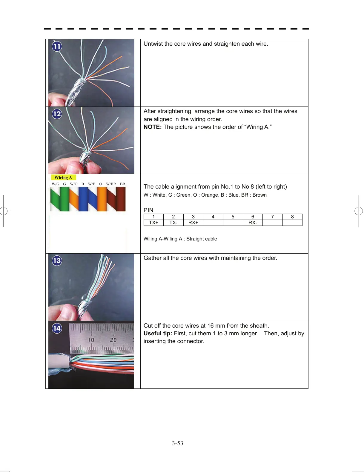
The cable alignment from pin No.1 to No.8 (left to right)
W : White, G : Green, O : Orange, B : Blue, BR : Brown
PIN
1 2 3 4 5 6 7 8
TX+ TX- RX+ RX-
Wiling A-Wiling A : Straight cable
Gather all the core wires with maintaining the order.
Cut off the core wires at 16 mm from the sheath.
Useful tip: First, cut
them 1 to 3 mm longer. Then, adjust by
inserting the connector.
W/G G W/O B W/B O W/BR B
R
Wirin
g
A
3-53
All manuals and user guides at all-guides.com

Table of Contents

Other manuals for JRC JMA-5312-6

Questions and Answers:

Question and Answer IconNeed help?

Do you have a question about the JRC JMA-5312-6 and is the answer not in the manual?

JRC JMA-5312-6 Specifications

General IconGeneral
BrandJRC
ModelJMA-5312-6
CategoryMarine Radar
LanguageEnglish

Related product manuals