Maintenance Guide
12-1
12. Electrical Components
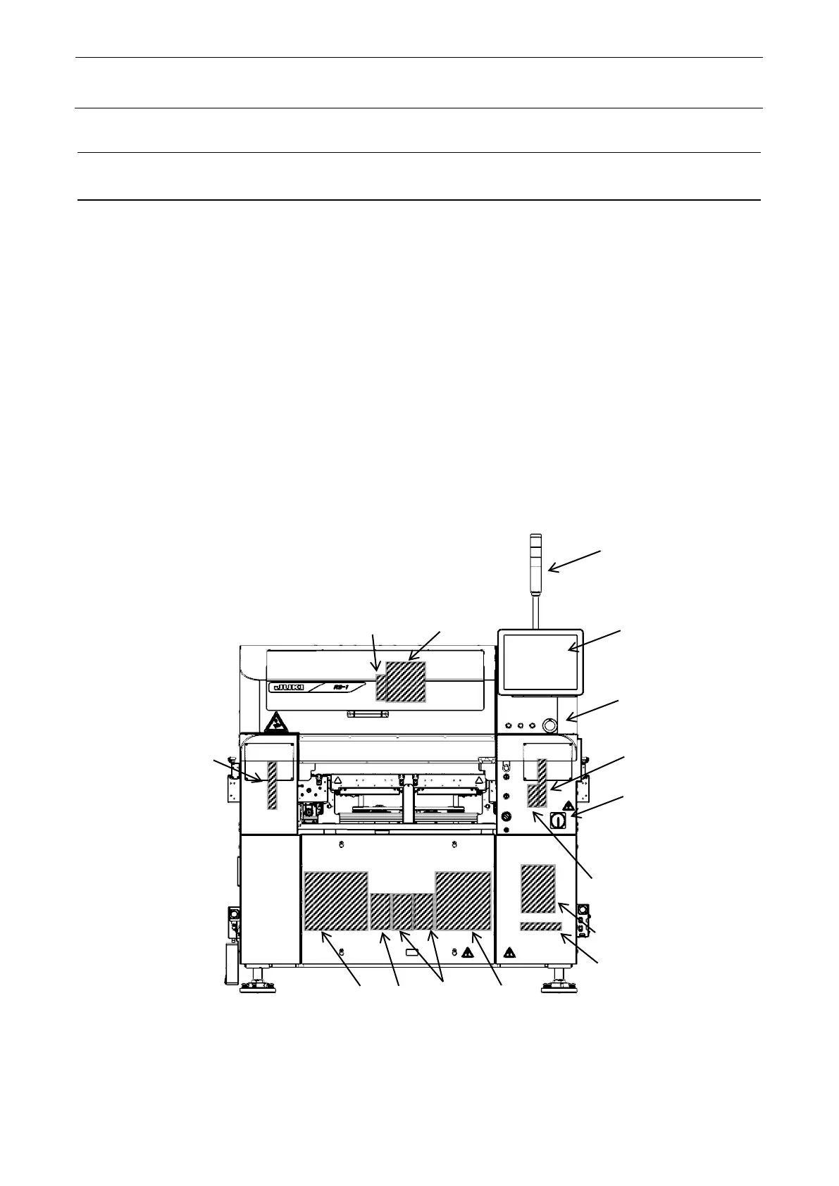
12-1 Layout of Electrical Components
1. Signal tower 2. LCD monitor 3. Operation panel
4. Head unit [Head main board assembly, Z/ZA/T-axis servo amplifier]
5. OCC camera, Vertical light board, Angle light board 6. Power switch
7. Control unit [CPU board, IO CONTROL PCB, POSITION BOARD, RS232 BOARD (OP),
IP-X11 PCB, CPCI BACK BOARD] 8. X-axis AC servo amplifier
9. Y-axis AC servo amplifier 10. Vacuum pump
11. 2-phase stepping motor driver [For L-motor and R-motor]
12. 5-phase stepping motor driver [For AWC-motor]
13. Driver for backup motor 14. VCS [BOTTOM LIGHT, BACK LIGHT, SIDE LIGHT, COAXIAL
LIGHT] 15. Power supply unit A 16. Power supply unit B
17. ATX power supply (with UPS function)
18. Transformer for AC power 19. Circuit breaker 20. SAFETY PCB
21. CONVEYOR PCB 22. E BANK RELAY PCB 23. LIGHT CONTROL PCB
24. SUPERIMPOSE BOARD 25. BATTERY
Figure 12-1-1 Front View