1-59
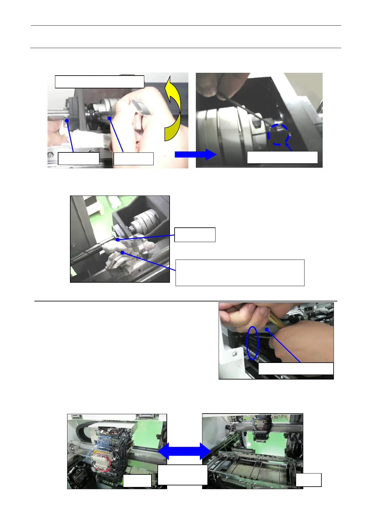
(11) Tighten the lock nut on the front with the wrenches 17 and 22. Tighten the set screw of the
lock nut.
(12) Tighten the lock nut on the rear with the wrenches 17 and 22.
∗ Put the wrench on the groove of the ball screw on the front.
1-7-4. Adjusting the Y Ball Screw
(1) Move the X_AXIS_FRAME_ASM to a front limit
where the wrench can be put, and then retighten
the screws (2 pcs.) (SM6062002TN) inside the
machine.
(2) Reciprocate the HEAD_UNIT several times until the X_AXIS_FRAME_ASM is in contact
with both the Y_STOPPER on the front and the Y_STOPPER on the rear to check that the
movement is smooth.
If the movement is not smooth, make the adjustment again from step 1-7-4 (1).
Before tightening the lock nut on the rear of
the ball screw, place clean cloth rags on
Wrench 22 turning direction