Art. No. SC 1000 KNX
4.2.4.1.3 Channel function "switching"
1-bit switching telegrams (ON, OFF) can be transmitted to the bus by using the channel function
"switching". In this way, it is possible to actuate lighting systems in combination with switch
actuators. Furthermore, the switching telegram can also be used in anther way for executing
other control tasks in the KNX system that match the 1-bit data format.
A KNX channel for switching has a display element and sensor surface in the graphic interface
for operation. The display area and sensor area, depending on the existing operation concept,
are combined into one surface (direct operation) or distributed on two surfaces (selection
operation).
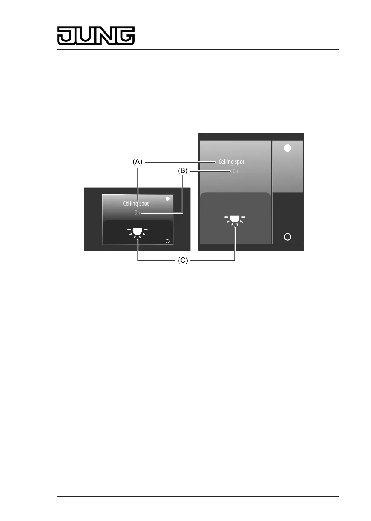
Figure 28: Example of an operating and display element of the channel function "switching"
left: direct operation / right: selection operation
(A) Text name
(B) Status text
(C) Status icon
i The channel function "switching" can be executed as a rocker or push-button function
depending on the ETS parameterisation. The figure shows the rocker configuration as an
example.
Status elements
The display area contains different display elements (figure 28) that are influenced by ETS
parameters. A name can be assigned to each KNX channel in the ETS (A). This text name is
centred in the display element for display whereby controllable KNX functions are identified for
the user (e.g. "ceiling spot"). In addition, a status text (B) can be displayed below the name,
which visualises different texts (e.g. "Off" / "On" or "Absent" / "Present") in the display
depending on the object value of the switching status feedback ("0" / "1"). After a device reset,
the display shows "---" until a feedback object value of the status text is received.
Similarly to the status text, a symbol (C) can be displayed in the lower display area. A
parameter in the ETS defines which type of status icon is used in the display element
(figure 29). This makes it possible to adapt the icon display to the activated function (e.g.
switching of lighting). The configured status icon changes depending on the switching state
thereby enabling the state of the controlled KNX channel to be read clearly (e.g. †: Lighting
OFF, ‡: Lighting ON).
The status text and icon can be omitted optionally.
Page 81 of 347
Software "Smart Control 501511"
Functional description
 Loading...