Art. No. SC 1000 KNX
4.2.4.2 Push-button extension module
Optionally, the number of control elements can be expanded by connecting a pushbutton
extension module to the Smart Control. The extension module extends the device to include up
to 4 mechanical control surfaces. Configuration and commissioning of the extension module is
clearly structured and easy to perform using the application program of the Smart Control.
4.2.4.2.1 Button configuration
During the button configuration, you define whether an extension module is connected to Smart
Control (basic unit). A push-button extension module expands the number of control surfaces in
addition to the sensor surfaces of the basic unit, so that up to four rockers or 8 buttons more are
available.
The rockers or buttons of the extension module are evaluated by the application program of the
basic unit. In addition, each control surface of the extension module has two status LEDs that
are also activated by the application program of the basic unit. Consequently, an extension
module does not have any application or bus coupling module of its own, and is configured and
put into operation in the ETS via the product database of the basic module. Each basic unit can
have only one extension module connected to it. Together, a basic unit and an extension
module form the "bus device unit".
Configuration of the control surfaces of the connected extension module is carried out in the
ETS on the parameter page "Push-button extension module -> Button configuration". The
parameter "Type of extension module" defines which extension module variant is connected to
the basic unit. Consequently, the parameter defines which control surfaces and status LED are
visible and configurable in the ETS. The setting "no TSEM" deactivates the module interface for
the push-button extension. In this case, there are no rocker or button parameters available in
the ETS for the extension module. Even the TSEM functions "Disable" (see page 163) and
"Alarm signalling" (see page 166), which are available as separate parameter pages, are then
not available.
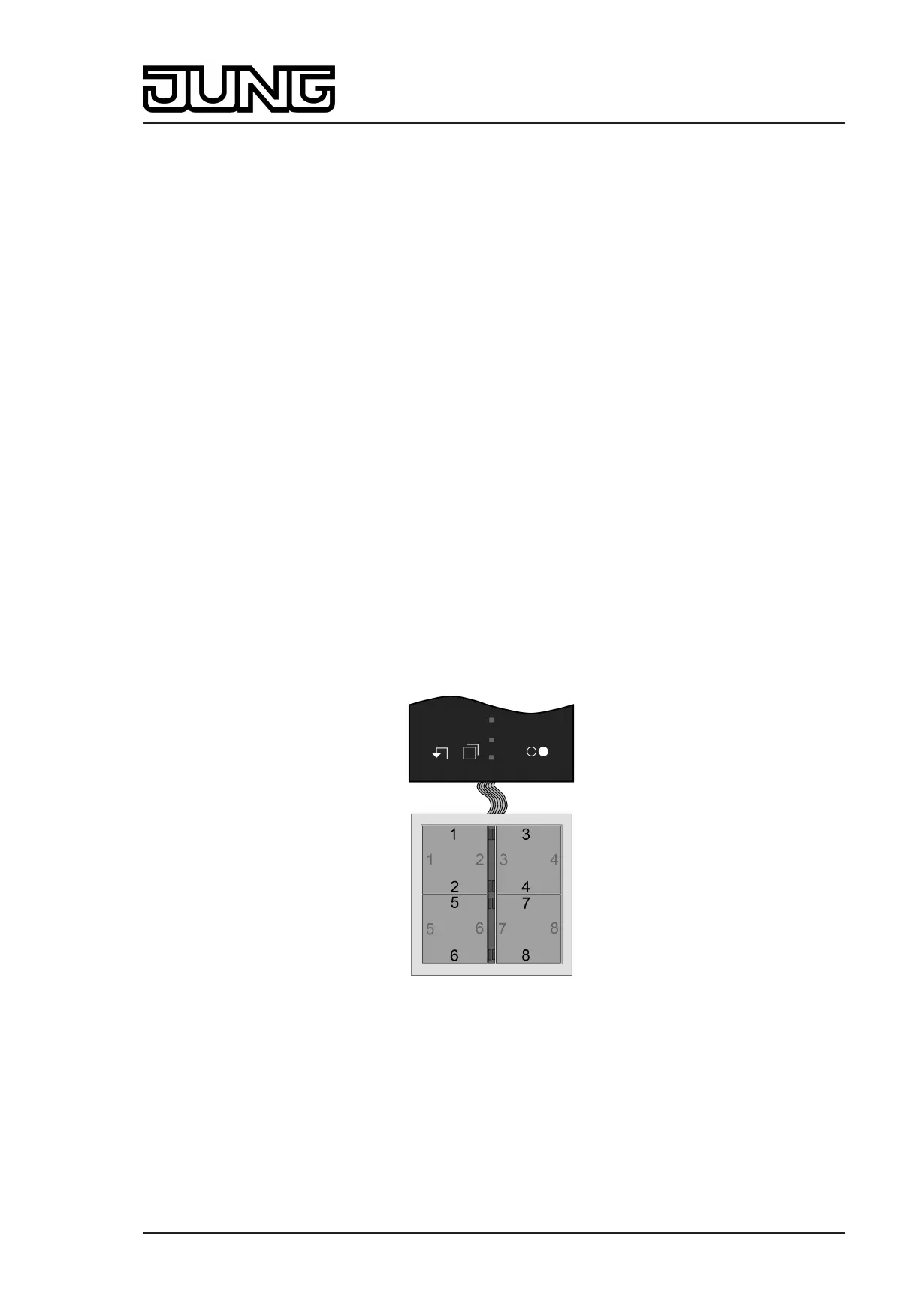
The module control surfaces enabled in this manner are identified in the ETS as module rockers
or module buttons. The rocker numbers or button numbers of the extension module are
assigned continuously to the buttons (figure 70).
Figure 70: Numbering of the module control surfaces
(demonstrated here based on the example of a 4-gang push-button extension module)
i For each button pair of a control surface configured in the ETS as a rocker function or as a
double-surface push-button function it is possible to set separately how the buttons are to
be arranged on the surface, i.e. where the actuation points are located (see
page 144-145). In the default setting the two actuation points of a control surface are
arranged vertically (top / bottom) . Alternatively the actuation points can be arranged
horizontally (left / right) .
Page 141 of 347
Software "Smart Control 501511"
Functional description
 Loading...