bandwidth over a relatively short sampling period (T1; 5 seconds), the measurement
approximates the peak bandwidth of the multicast stream.
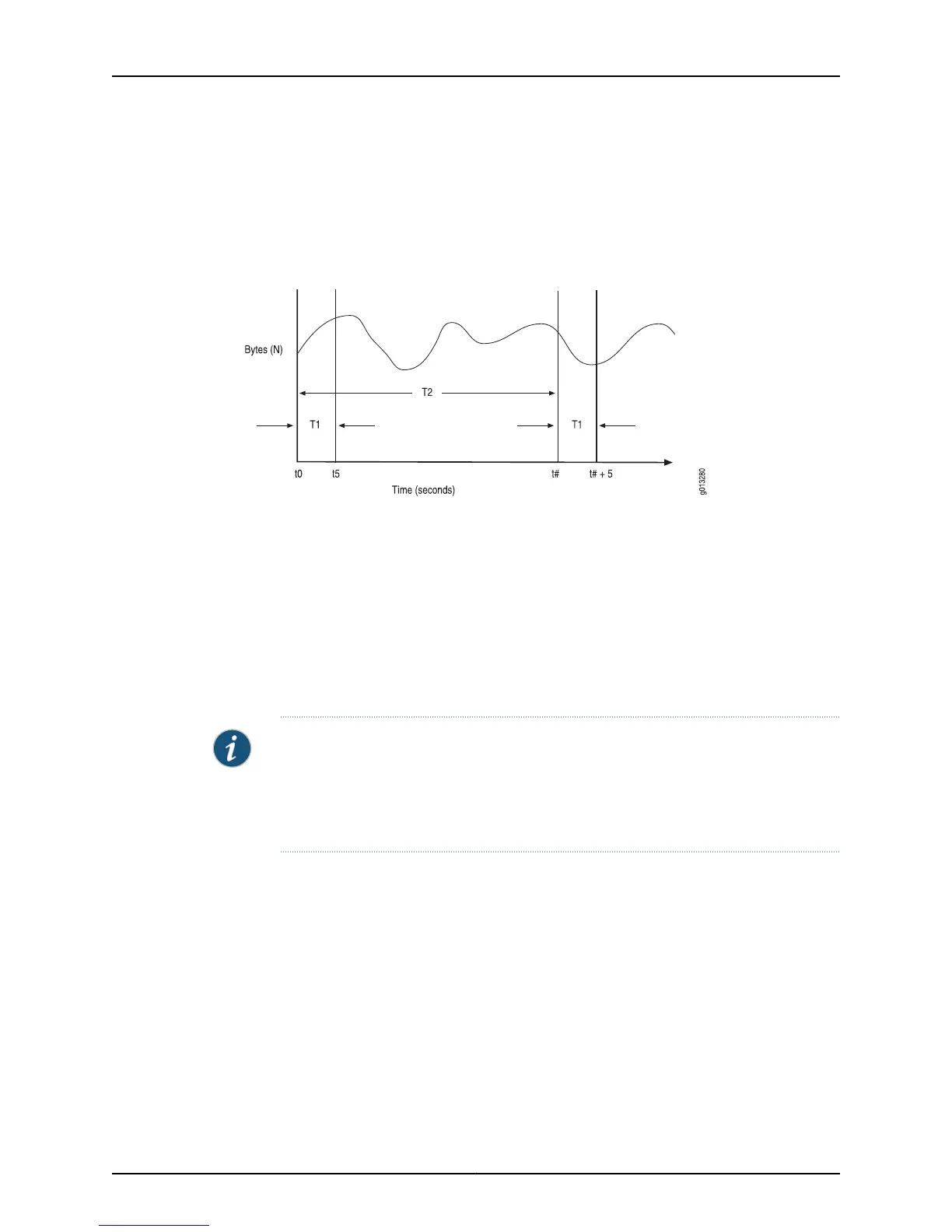
As an example, assume that a new mroute (S1, G1) is added to the interface controller
(IC) at time t0.
Figure 1: Example of Adaptive IPv4 Multicast Bandwidth Detection
To calculate the measured bandwidth of a stream, the router uses the following equation:
R = (N
t+5
– N
t
) / 5
Where
R = Calculated bandwidth of the stream during each sampling interval
N
t
= Bytes measured at the start of each sampling period (t seconds)
N
t+5
= Bytes measured at the end of each sampling period (t+5 seconds)
NOTE: When the mroute is first installed in the FC (at t = 0), R
0
is undetermined. For
multicast admission control no joins are admitted until the first bandwidth measurement
is computed (that is, for admission control, R0 is considered to be infinite). Similarly,
no QoS adjustment occurs until the first bandwidth measurement is computed (that
is, for QoS adjustment, R0 is considered to be zero [0]).
Using the previous graph as a reference, the first bandwidth rate (R1
0
) and at time t
5
(N
5
)
and the bytes received values are subtracted and divided by the sampling period T
1
to
yield the average rate. This process is repeated every sampling interval, T
2
, to yield rates
R1, R2, R3, and so on.
The first two sampling interval calculations are as follows:
R
1
= (N
5
- N
0
)/5
R
2
= (N
#+5
- N
#
)/5
Copyright © 2010, Juniper Networks, Inc.12
JunosE 11.2.x Multicast Routing Configuration Guide