TECHNICAL DESCRIPTION MULTICAL
®
401
5512-091 GB/02.2008/Rev. J1
49
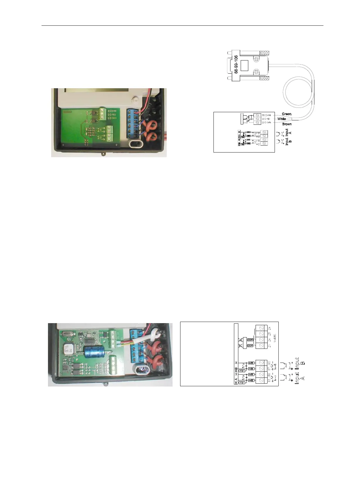
11.2 Data/pulse inputs (66-0R)
Figure 38 Figure 39
The data connection in this module is identical with that described earlier.
Two extra pulse signals, e.g. from cold-water and hot-water meters, can also be connected to the meter. Meters
with both Reed switch and transistor output can be connected. The inputs have a max. input frequency of
0.5
Hz.
Reed switches with built-in protective resistances of up to 1 kOhm can be used and both Input A and Input B
contains the necessary de-bouncing for Reed switches.
No Darlington transistors should be used when connecting the transistor outputs to Input A and Input B, as the
voltage level at logical”0” must be
0.5 V. In addition, the leak current in the output must be less than 1 A.
The pulse inputs can be configured for most cold-water and hot-water meters.
See section 3.3.3
>FF< Input a, >GG< Input b for information on configuration of pulse values and maximum
flowrate. Required configuration must be stated when ordering. Reconfiguration can be done by the use of the PC-
program METERTOOL.
11.3 M-Bus, EN 1434, EN 13757/pulse inputs (66-0P)
M-Bus, EN 1434/pulse inputs (66-0S)
Figure 40 Figure 41
The M-Bus modules are used for remote reading of MULTICAL
®
401 via an M-Bus net work.
To make an M-Bus system work, it is necessary to give each M-Bus module a unique address. The M-Bus address
is automatically generated based on the customer meter number, and can easily be changed either by means of
the hand-held terminal MULTITERM or by means of the PC program of METERTOOL.