Operating and appliance data
© KEB, 2008-02 COMBIVERT R6-S Page 3.2 - 5
3
10
3.2.4 Description of the ru parameters
Legend:
Addr. = Address
PG = programmable →
+ = programmable
- = non-programmable
E = Enter →
+ = yes
- = no
R = right →
ro = read-only
rw = reading and writing
KB = keyboard
Min. value = Min. value
Max. value = Max. value
Res. = Resolution
Default = Default value
[?] = Unity
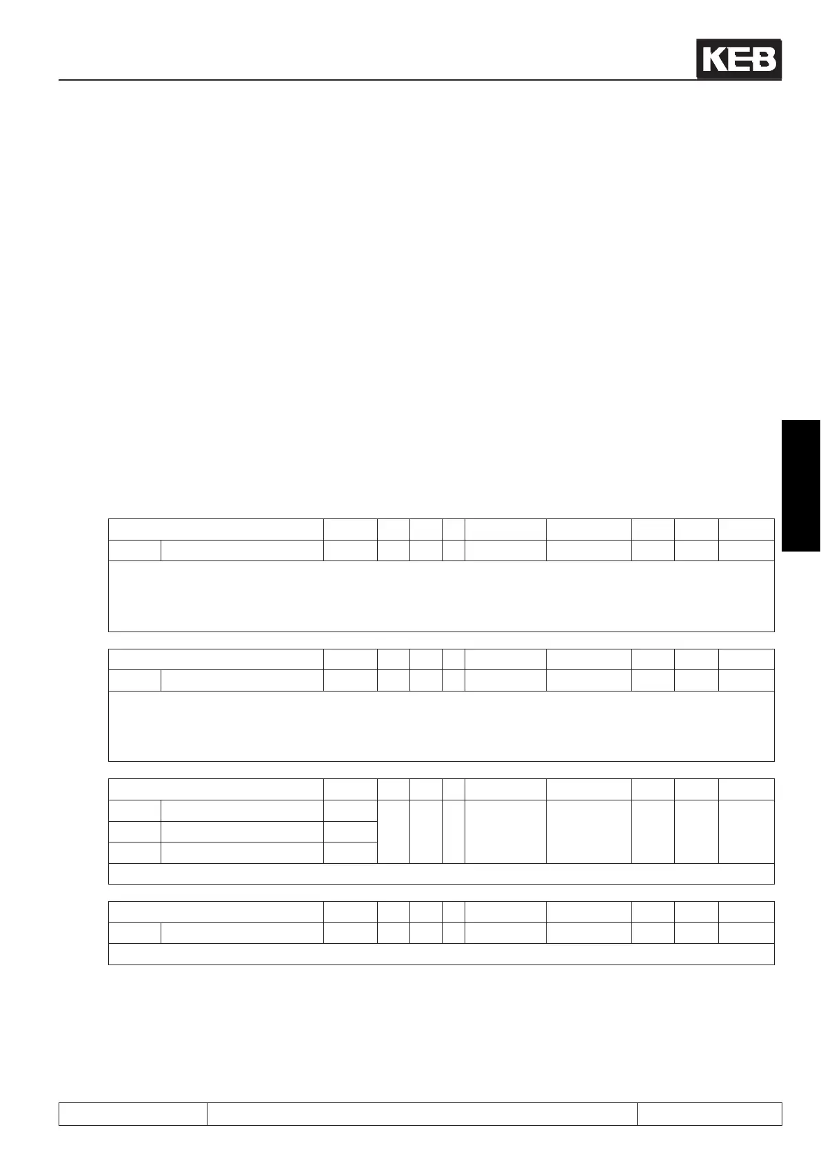
Parameter Addr. R PG E Min. value Max. value Res. [?] Default
ru.00 Inverter state 0200h ro - - 0 255 1 - 0
The inverter state displays the actual operating condition of the regenerative unit. The actual error message
is displayed in error case, even if the display is already reset by ENTER (error LED in the operator is still
ashing).Status messages and information about the cause and removal are described in chapter 5 „Error
diagnosis“.
Parameter Addr. R PG E Min. value Max. value Res. [?] Default
ru.03 Actual line frequency 0203h ro - - -320.00 320.00 0.01 Hz -
The actual line frequency is determined during the initialization phase after switching on. Slowly changes of
the line frequency during the operation are recognized and displayed in ru.03. If the COMBIVERT R6-S is in
„netof“, ru.03 displays the actual regenerative frequency.
Positivevaluesmeanaclockwiserotatingeldandnegativevaluesananti-clockwiserotatingeld.
Parameter Addr. R PG E Min. value Max. value Res. [?] Default
ru.08 AC current L1 0208h
ro - - 0,0 6553,5 0,1 A 0,0ru.09 AC current L2 0209h
ru.10 AC current L3 020Ah
Display of the actual input current of the respective phase.
Parameter Addr. R PG E Min. value Max. value Res. [?] Default
ru.11 Input voltage 020Bh ro - - 0 1000 1 V -
Display of the actual mains voltage
 Loading...

