45
6-10 Valve Clearance Adjustment
Remove cylinder head cover
Remove the cylinder head side cover.
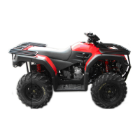
Remove left crankcase cover, and turn the
drive face, and align the timing mark on the
cam sprocket with that of cylinder head,
piston is at TDC position.
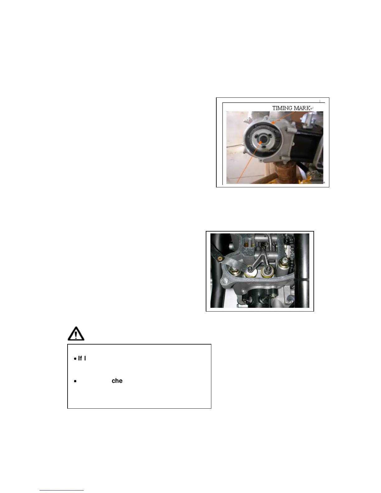
Loosen valve clearance adjustment nuts
and bolts located on valve rocker arm.
Measure and adjust valve clearance with
feeler gauge.
After valve clearance had been adjusted
to standard value, hold adjustment bolt
and then tighten the Adjustment nut.
Standard Value: IN 0.10 ± 0.02 mm
EX 0.15 ± 0.02 mm
Install the cylinder head side cover.
Start the engine and make sure that
engine oil flows onto the cylinder head.
Stop the engine after confirmed, and
then install the cylinder head cover
and AI pipe
Caution
˙
˙˙
˙
If lubricant does not flow to cylinder head,
engine components will be worn out
seriously. Thus, it must be confirmed.
˙
˙˙
˙
When checking lubricant flowing
condition, run the engine in idle speed. Do
not accelerate engine speed.