2100-900-01 Rev. D / September 2011 Return to Section Topics 3-3
Model 2100 6 1/2-Digit Resolution Digital Multimeter User’s Manual Section 3: Basic Measurement Functions
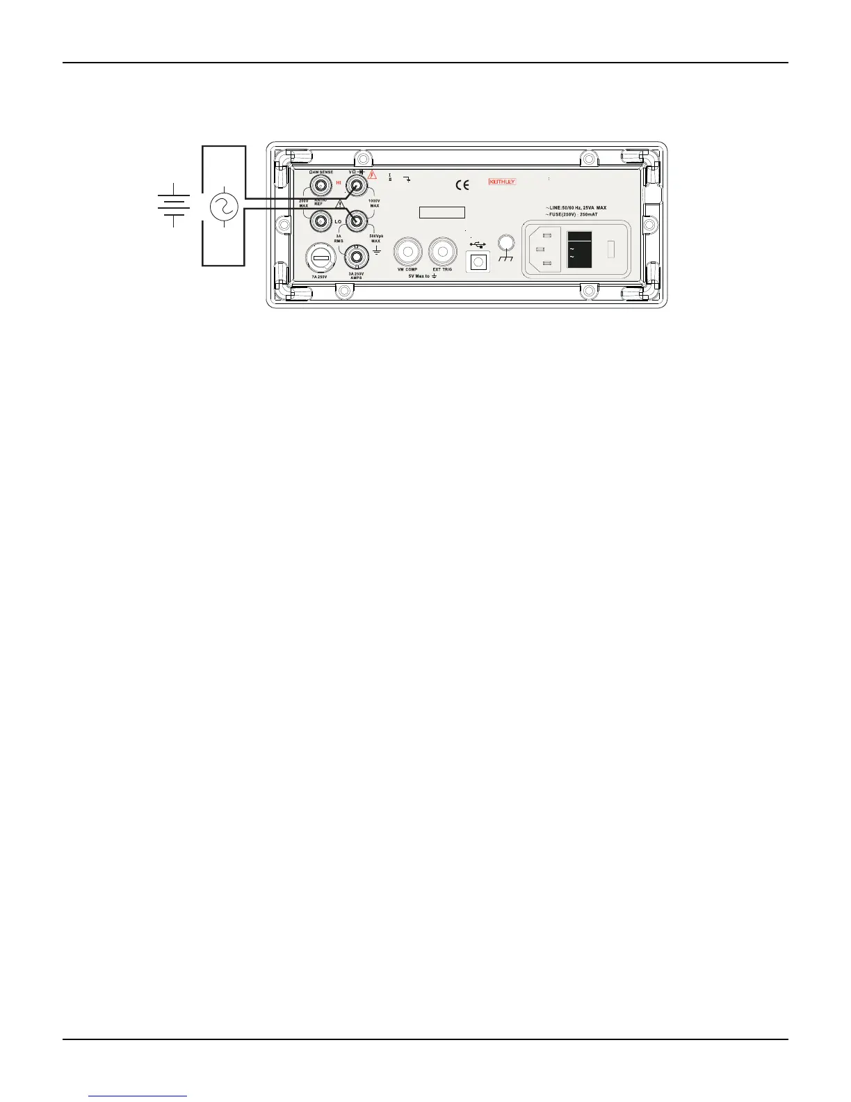
Figure 3-3
Model 2100 rear panel input terminals
NOTE Follow the same procedure when using either the front or rear panel terminals (refer to
Figure 3-3).
How to measure voltage
1. Select input signal connections on front or rear panel.
2. Connect the test leads to the terminals as shown in Figure 3-1 (DC) or Figure 3-2 (AC).
3. Set the resolution of DCV (refer to “Resolution setting (digits)” in Section 4), bandwidth of
ACV (refer to “AC filter” in Section 4) or skip this step if the default settings are used.
4. Press the DCV or ACV key for DC or AC voltage measurement.
5. Select the auto-range function by pressing the AUTO key on the front panel, or use the up
and down arrow keys to select the desired range.
6. Connect the test leads to your source signal and observe the reading shown on the display.
If the input signal is beyond the allowed range, an overflow message ("OVLD") will be
displayed.
Current measurements (DC and AC)
The ranges for DC current measurements for the Model 2100 are 10mA, 100mA, 1A, and 3A, with
a sensitivity of 10NA. For AC current measurements, the range is 1A to 3A RMS with a sensitivity
of 10
A. Figures 3-4 and 3-5 illustrate how to measure DC/AC currents with the Model 2100.
CAUTION The maximum input current allowed is 3A, 250V. Do not apply excess current
to your meter to avoid damaging the fuse of current input.
How to measure current
1. Select input signal connections on front or rear panel.
2. Connect the test leads to the terminals as shown in Figure 3-4.
3. Set the resolution of DCI (refer to “Resolution setting (digits)” in Section 4), and bandwidth
of ACI (refer to “AC filter” in Section 4), or skip this step if the default setting is used.
4. Press SHIFT + DCV or SHIFT + ACV keys for DCI or ACI measurement.
5. Select the auto-range function by pressing the AUTO key on the front panel, or use the up
and down arrow keys to select the desired range.
6. Connect test leads to your source signal and observe the reading shown on the display. If
the input signal is greater than the allowed range, an overflow message ("OVLD") will be
displayed.
AC
VM
CAT 1000V
CAT 600V
LINE
120V120V
240V240V
24
0V2
4
0V
*T w0 00 01 00 0*
MADE IN
TA IWA N
NO INTERNA L SERVICEABLE PARTS, SERVICE
WARNING
BY QUALIFIED PERSONNEL ONLY.
FOR CONTINUED PROTECTION AGA INST FIRE HAZA RD.
CAUTION:
REPLACEFUSEWITHSAMETYPEANDRATING.
DC
VM
or
VM = Voltage measurement