2100-900-01 Rev. D / September 2011 Return to Section Topics 3-9
Model 2100 6 1/2-Digit Resolution Digital Multimeter User’s Manual Section 3: Basic Measurement Functions
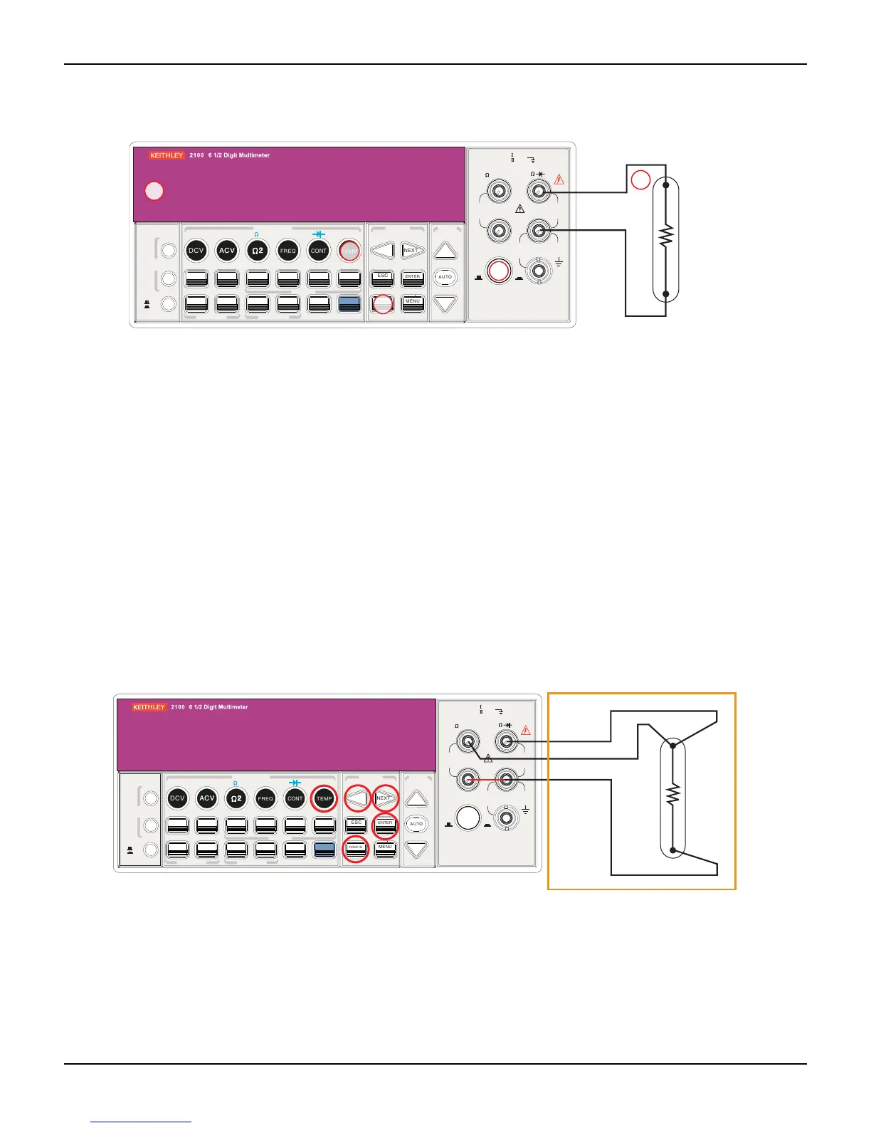
Figure 3-12
Theory diagram of 2-wire RTD measurement
To take an RTD measurement:
1. Use the terminals switch to select the front terminals.
2. Connect the low thermal leads as shown in Figure 3-12.
3. Configure sensor type and unit using CONFIG + TEMP or the PREV and NEXT keys. When
ready, press the ENTER key.
4. Press the TEMP key.
5. Place the RTD at the measurement point and read the display.
3-wire RTD measurements
How to measure temperature with a 3-Wire RTD
Figure 3-13 shows a theory diagram of a 3-wire RTD measurement:
Figure 3-13
Theory diagram of 3-wire RTD measurement
To measure temperature with a 3-wire RTD:
1. Measure the third wire using the 4-wire resistance measurement function (detailed later in
this section).
2. Select USER RTD as the sensor:
a) Press the CONFIG key.
b) Next, press the TEMP key.
FILTER
NEXT
PREV
DIGITS
RATIO
%
MIN/MAX
NULL
ESC
ENTER
AUTO
SINGLE
TRIGGER
STORE
RECALL
LOCAL
SHIFT
CONFIG
MENU
AUTO
DCV
ACV
22
FREQ
CONT
TEMP
4 WIRE
RATIO
V
INPUT
PEAK
200V
PEAK
HI
LO
PEAK
500V
3A
RMS
INPUTS
3A 250V
FRONT/REAR
AMPS
R
1000V
REF
CAT 1000V
CAT 600V
LOCK
SETUP
ACV
22
FUNCTION
DCI ACI
4
PERIOD
LIMITS MX+B
dB
EXTRIG
HOLD
MATH
TRIGGER MEMORY
dBm
RANGE
DISPLAY
NEXT
PREV
POWER
OFF
ON
SENSE
F
4
5
Platinum
RTD
Note: Source current flows from the INPUT HI to
INPUT LO terminals.
Input HI
Input LO
FILTER
NEXT
PREV
DIGITS
RATIO
%
MIN/MAX
NULL
ESC
ENTER
AUTO
SINGLE
TRIGGER
STORE
RECALL
LOCAL
SHIFT
CONFIG
MENU
AUTO
DCV
ACV
22
FREQ
CONT
TEMP
4 WIRE
RATIO
V
INPUT
PEAK
200V
PEAK
HI
LO
PEAK
500V
3A
RMS
INPUTS
3A 250V
FRONT/REAR
AMPS
R
1000V
REF
CAT 1000V
CAT 600V
LOCK
SETUP
ACV
22
FUNCTION
DCI ACI
4
PERIOD
LIMITS MX+B
dB
EXTRIG
HOLD
MATH
TRIGGER MEMORY
dBm
RANGE
DISPLAY
NEXT
PREV
POWER
OFF
ON
SENSE
F
Platinum
RTD
Sense Ω3-wire HI
Input HI
Input LO