3-8 Return to Section Topics 2100-900-01 Rev. D / September 2011
Section 3: Basic Measurement Functions Model 2100 6 1/2-Digit Resolution Digital Multimeter User’s Manual
WARNING The positive end of the source signal must be connected to the HI input
terminals, and the negative end to the LO input terminals.
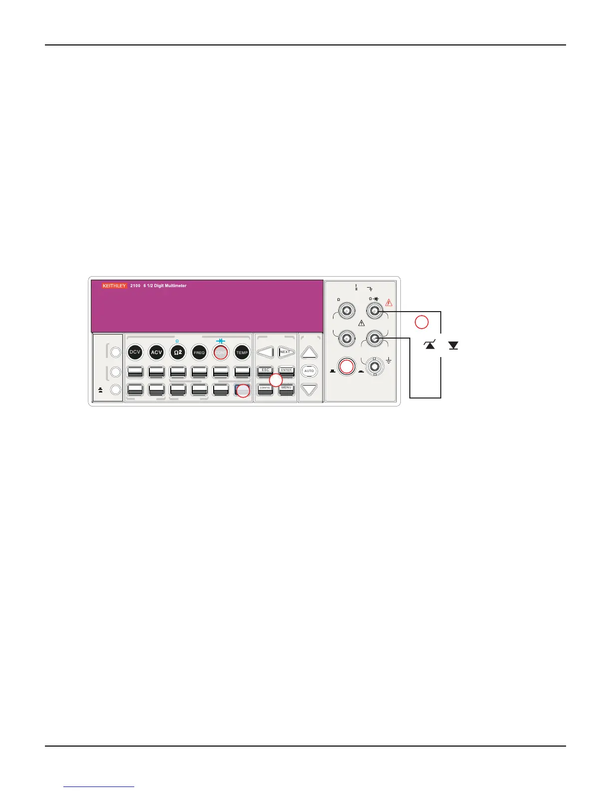
How to measure a diode
1. Select input signal connections on the front or rear panel.
2. Connect the diode to the terminals. For forward bias, connect the probe from the HI input
terminal to the positive end of the diode, and connect the probe from the LO input terminal
to the negative end of the diode.
3. Set voltage bound by pressing CONFIG + SHIFT + CONT keys. When ready, press
ENTER, or skip this step if the default voltage bound is used.
4. Press the SHIFT + CONT keys to select the diode testing function and observe the reading
on the display.
Figure 3-11
Model 2100 general purpose diode
RTD measurements
There are three techniques that can be used to measure temperature with RTDs: 2-wire, 3-wire,
and 4-wire measurements. You will find connection instructions and measuring procedures in the
following subsections.
2-wire RTD measurements
How to measure temperature with a 2-wire RTD
Figure 3-12 shows a theory diagram of 2-wire RTD measurement.
FILTER
NEXT
PREV
DIGITS
RATIO
%
MIN/MAX
NULL
ESC
ENTER
AUTO
SINGLE
TRIGGER
STORE
RECALL
LOCAL
SHIFT
CONFIG
MENU
AUTO
DCV
ACV
22
FREQ
CONT
TEMP
4 WIRE
RATIO
V
INPUT
PEAK
200V
PEAK
HI
LO
PEAK
500V
3A
RMS
INPUTS
3A 250V
FRONT/REAR
AMPS
R
1000V
REF
CAT 1000V
CAT 600V
LOCK
SETUP
ACV
22
FUNCTION
DCI ACI
4
PERIOD
LIMITS MX+B
dB
EXTRIG
HOLD
MATH
TRIGGER MEMORY
dBm
RANGE
DISPLAY
NEXT
PREV
POWER
OFF
ON
SENSE
F
3
2
1
4
or
Note: Source current flows from the INPUT HI to
INPUT LO terminals.
Zener
diode
General-purpose
diode