2100-900-01 Rev. D / September 2011 Return to Section Topics 4-17
Model 2100 6 1/2-Digit Resolution Digital Multimeter User’s Manual Section 4: Front Panel Operations
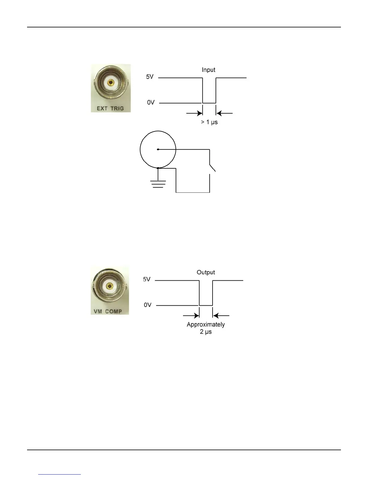
Figure 4-11
Ext Trigger input
VM COMP (Voltmeter Complete) Terminal
The rear panel VM COMP terminal provides a low-true pulse after finishing each measurement.
The VM COMP and external trigger shown below provides a standard hardware handshake
sequence between measurement and switching devices (see
Figure 4-12).
Figure 4-12
VM COMP Trigger output
Remote interface operation (software or internal trigger)
Software trigger: Software triggering is similar to single triggering, but instead of using the
SINGLE key on the front panel, you send a command from your PC to the multimeter to generate
an event. Use the following command from your PC terminal to set the trigger source:
TRIGger:SOURce BUS
Internal trigger: The Internal Trigger is the default trigger mode for the remote interface operation.
In the Internal Trigger mode, a trigger signal will be issued whenever the multimeter is in the
wait-for-trigger state. To set the internal trigger, use the following command from your PC terminal:
TRIGger:SOURce IMMediate