1-8 Getting Started Model 6487 Reference Manual
Front panel operation
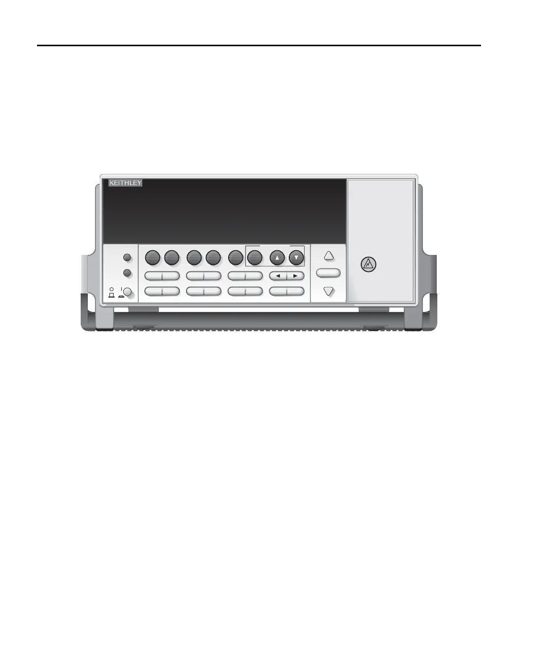
Figure 1-2 shows the front panel of the Model 6487. For a detailed description of the vari-
ous controls, displays, and indicators, see Section 1 of the Model 6487 User’s Manual.
Figure 1-2
Front panel
Status and error messages
Status and error messages are displayed momentarily. During operation and programming,
you will encounter a number of front panel messages. Typical messages are either of status
or error variety, as listed in Appendix B.
Messages, both status and error, are held in queues. For information on retrieving mes-
sages from queues, see Section 10.
Default settings
The Model 6487 can be restored to one of five setup configurations: factory default
(FACT), three user-saved (USR0, USR1, and USR2), and bus default (GPIB). As shipped
from the factory, the Model 6487 powers up to the factory default settings. Factory default
settings provide a general purpose setup for front panel operation, while the bus default
(GPIB) settings do the same for remote operation. Factory and GPIB default settings are
listed in Table 1-2.
The instrument will power up to whichever default setup was saved as the power-on setup.
klqb At the factory, the factory default setup is saved into the USR0, USR1, and USR2
setups.
6487 PICOAMMETER /VOLTAGE SOURCE
RANGE
AUTO
CONFIG/
LOCAL
MENU
POWER
RANGE
EXIT ENTER
LIMIT
RATEDIGITS
STORE RECALL
I | Ω
MATH FILT ZCHK REL OPER
COMM
DISP
TRIG
AZERO DAMP
SAVE SETUP
V-SOURCE
VOLTAGE
SOURCE
OPERATE
 Loading...


