9-6 Remote Operation Model 6487 Reference Manual
To connect the Model 6487 to the IEEE-488 bus, follow these steps:
1. Line up the cable connector with the connector located on the rear panel. The con-
nector is designed so that it will fit only one way. Figure 9-3 shows the location of
the IEEE-488 connector.
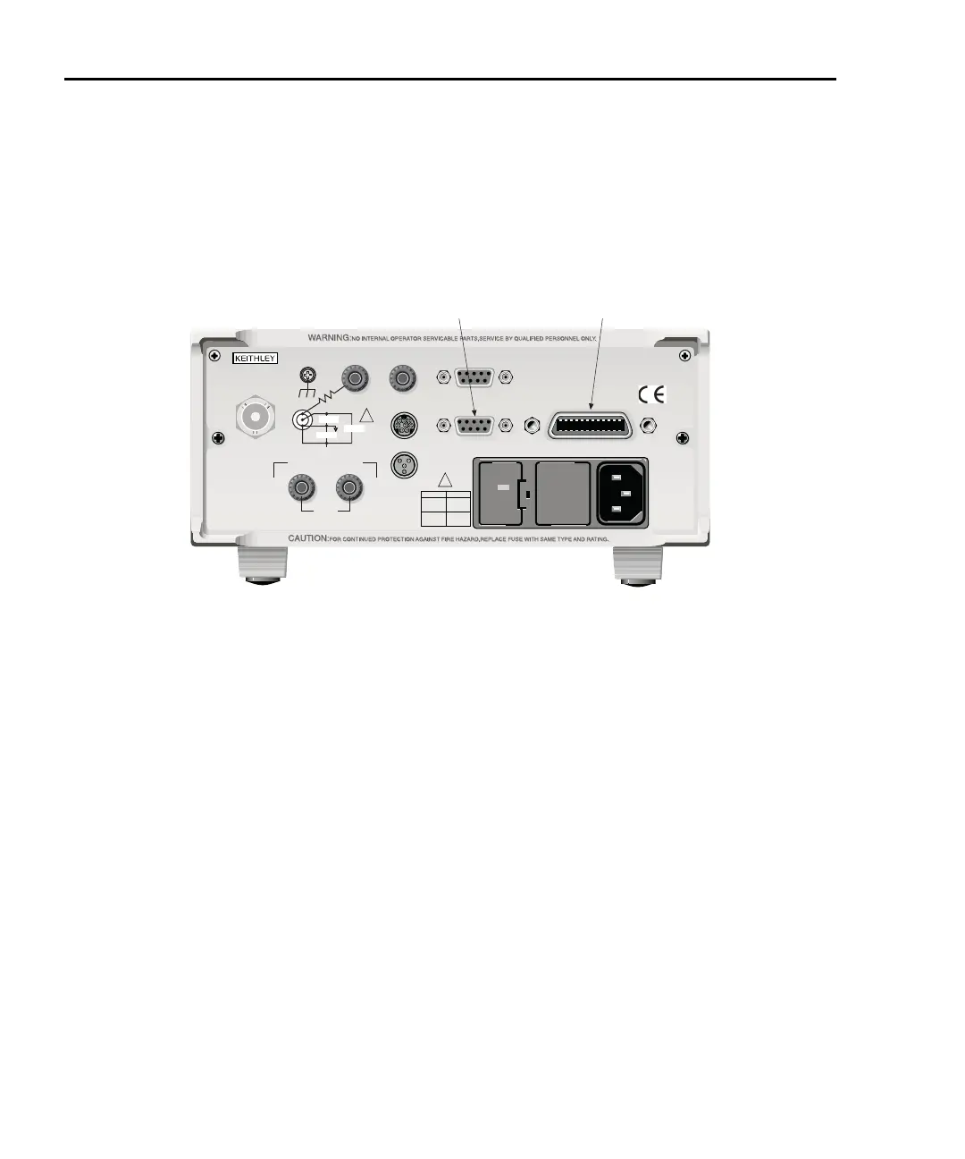
Figure 9-3
IEEE-488 and RS-232 connector locations
2. Tighten the screws securely, making sure not to over tighten them.
3. Connect any additional connectors from other instruments as required for your
application.
4. Make sure that the other end of the cable is properly connected to the controller.
Most controllers are equipped with an IEEE-488 style connector, but a few may
require a different type of connecting cable. See your controllers instruction man-
ual for information about properly connecting to the IEEE-488 bus.
klqb You can only have 15 devices connected to an IEEE-488 bus, including the con-
troller. The maximum cable length is either 20 meters or two meters times the
number of devices, whichever is less. Not observing these limits may cause
erratic bus operation.
Primary address
The Model 6487 ships from the factory with a GPIB address of 22. When the instrument
powers up, it momentarily displays the primary address. You can set the address to a value
of 0-30. Do not assign the same address to another device or to a controller that is on the
same GPIB bus.
120
LINE RATING
50, 60Hz
50 VA MAX
INPUT
(CHANGE IEEE ADDRESS
WITH FRONT PANEL MENU)
IEEE-488
CAT I
TRIGGER LINK
RS-232
MADE IN
U.S.A.
ANALOG OUT
DIGITAL I/O
505V
MAX
V-SOURCE OUTPUT
505V PK TO CHASSIS
LO HI
INTERLOCK
!
!
FUSELINE
400mAT
(SB)
100 VAC
120 VAC
200mAT
(SB)
220 VAC
240 VAC
505V PK
505V PK
505V PK
IEEE-488RS-232