Model 6487 Reference Manual Applications Guide G-19
Capacitor leakage current
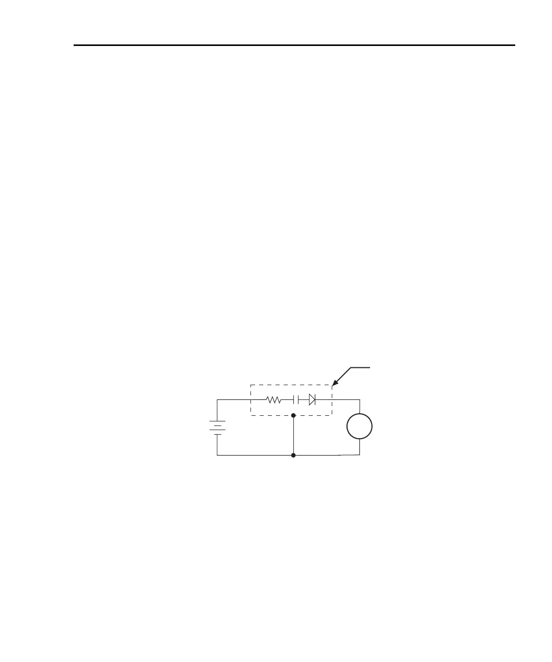
Figure G-15 shows how to measure the leakage current for a capacitor. The magnitude of
the leakage is dependent on the type of dielectric and the applied voltage.
A resistor and a diode are used to limit noise for the measurement. The resistor limits the
current in case the capacitor becomes shorted, and it also offsets the effects of decreasing
capacitive reactance with increasing frequency, which affects picoammeter noise perfor-
mance (see “Source capacitance,” page G-6). A good starting point is to choose a resis-
tance value that results in an RC time constant of 0.5 to 2 seconds. (See Table G-1 for
minimum recommended resistance values based on measurement range.) The diode acts
like a variable resistance, low while the capacitor is charging, and much higher when the
capacitor is fully charged. As a result, the resistance value can be significantly smaller.
Also damping may help to reduce noise (see “Damping,” page 4-8).
For this test, a fixed bias voltage is to be applied to the capacitor for a specified time to
allow the capacitor to fully charge (current decays exponentially with time). The leakage
current is then measured. After the measurement, the voltage source is set to output 0V for
a specified time to allow the capacitor to discharge. Note that measurements with the volt-
age source in the high-impedance state (from interlock opening) might have high noise
pickup caused by an unshielded voltage source HI terminal.
Figure G-15
Connections; capacitor leakage current test
Measuring high resistance
The Model 6487 can be used to make high resistance (>1GΩ) measurements using the
built-in voltage source. The alternating voltage ohms mode (Section 3) can be used to
improve accuracy and repeatability of very high resistance measurements. High resistance
measurement applications include insulation resistance testing and resistivity measure-
ments of insulators.
6487
V-Source
A
+
-
6487
Picoammeter
Metal
Shield
HI
LO
HI
LO
Equivalent Circuit

 Loading...


