Model 6487 Reference Manual Applications Guide G-17
Zero check on / off response
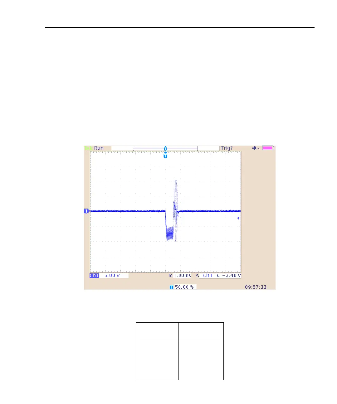
Figure G-13 shows the transient that can be expected from input HI to LO during a change
in the zero check mode with no input current. The transition is similar for entering and
leaving zero check. For current ranges 2μA and below, the magnitude of the response is
not as large, but similar in duration. As with range change transients, the zero check tran-
sient is presented through an internal impedance which will limit the resulting current
through the DUT (Table G-2). If there is an input current while in zero check, the input
voltage will depend on the current and the zero check input impedance for the specific
range.
Figure G-13
Zero check transient
Table G-2
Internal impedance for zero check transient
Range Zcheck
Transient
impedance
2mA,20mA 500Ω
20μA,200μA 50kΩ
200nA,2μA3.5MΩ
2nA,20nA 11MΩ
 Loading...


