G-20 Applications Guide Model 6487 Reference Manual
To measure high resistance, the internal voltage source is placed in series with the
unknown resistance and the picoammeter. Since the voltage drop across the picoammeter
is negligible, essentially all the voltage appears across the unknown resistance. The result-
ing current is measured by the picoammeter. The resistance is then calculated and dis-
played using Ohm's Law:
where: V is the sourced test voltage
I is the measured current
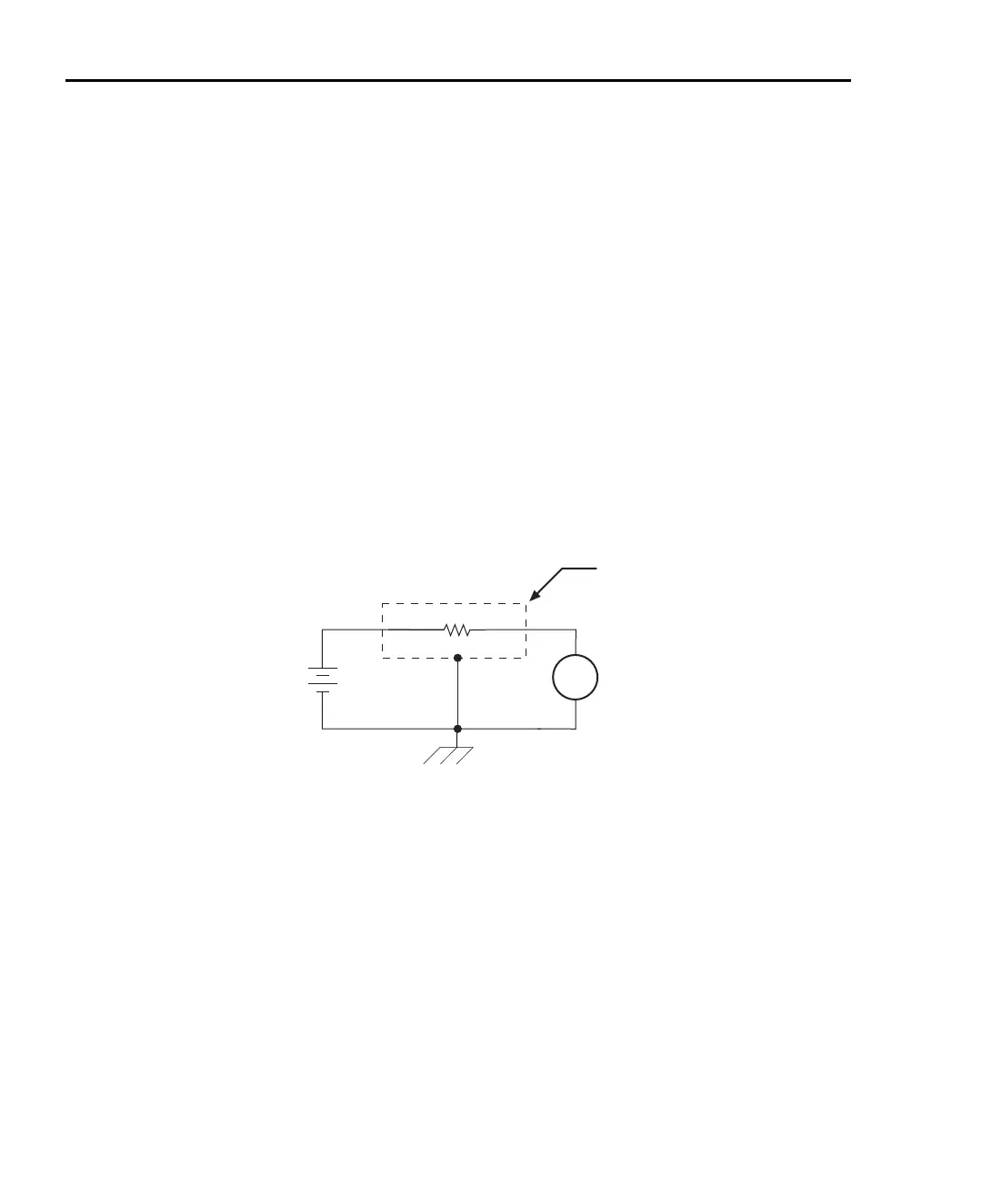
The basic configuration for measuring high resistance using the Model 6487 Picoammeter
is shown in Figure G-16. The HI terminal of the Model 6487 picoammeter is connected to
one end of the unknown resistance (R) and the HI terminal of the internal voltage source to
the other end of the resistance. The LO terminal of the picoammeter is connected to the
LO terminal of the voltage source. Both LO terminals are also connected to earth ground.
This should be done via the ground link on the rear of the Model 6487.
Figure G-16
Measuring high resistance using the 6487
To prevent generated current due to electrostatic interference, place the unknown resis-
tance in a shielded test fixture. The metal shield is connected to the LO terminal of the
6487.
Alternating voltage ohms measurement
To reduce measurement errors caused by background currents, use the alternating voltage
ohms measurement mode. The step voltage and time for each phase should be carefully
chosen to assure proper circuit settling, while the averaging a number of reading cycles
will improve repeatability. See “Alternating voltage ohms mode,” page 3-21 in Section 3
for details.
6487
V-Source
(V)
A
+
-
6487
Picoammeter
Unknown Resistance
(R)
Measured
Current
Metal
Shield
HI
LO
HI
LO
Equivalent Circuit

 Loading...


