Model 6487 Reference Manual Triggering 7-13
Output trigger specifications
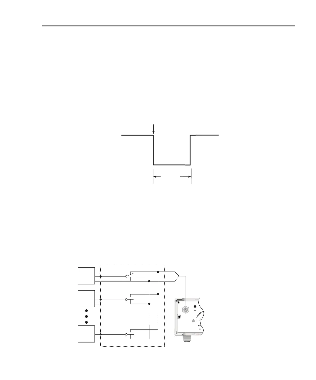
The Model 6487 can be programmed to output a trigger immediately after a measurement
and/or when operation leaves the trigger layer of the trigger model. The output trigger pro-
vides a TTL-compatible output pulse that can be used to trigger other instruments. The
specifications for this trigger pulse are shown in Figure 7-6. A trigger link line can source
1mA and sink up to 50mA.
Figure 7-6
Trigger link output pulse specifications
External trigger example
In a simple test system, you may want to close a switching channel and measure the cur-
rent from a DUT connected to that channel. Such a test system is shown in Figure 7-7.
This example uses a Model 6487 to measure 10 DUTs switched by a Model 7158 low cur-
rent card in a Model 7001 or 7002 switch system.
Figure 7-7
DUT test system
Meter Complete
TTL High
(3.4V Typical)
TTL Low
(0.25V Typical)
5μs
Minimum
120
FUSE LINE
630mA
LINE RATING
50, 60Hz
30 VA
T
(SB)
100 VAC
120 VAC
315mAT
(SB)
220 VAC
240 VAC
!
INPUT
(CHANGE IEEE ADDRESS
WITH FRONT PANEL MENU)
IEEE-488
CAT I
TRIGGER LINK
RS-232
MADE IN
U.S.A.
RANGE
DEPENDENT
ANALOG OUT
DUT
#2
DUT
#1
DUT
#10
7158 Low Current Card
OUTPUT
Model 6487
Picoammeter
DUT
#3-#9
LO

 Loading...


