Model 6487 Reference Manual Applications Guide G-21
Cable insulation resistance
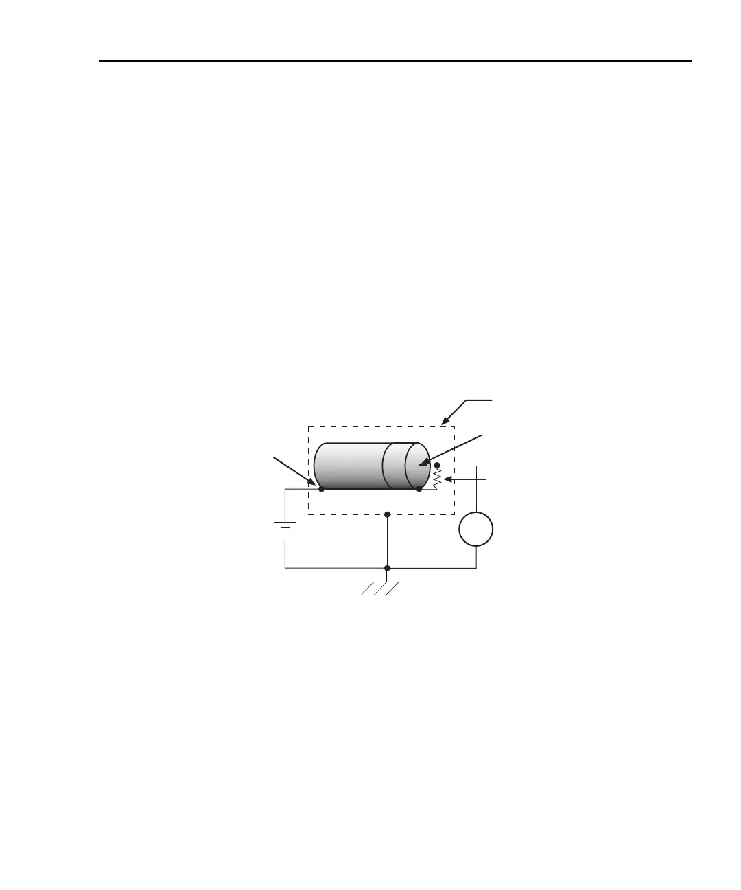
Figure G-17 shows how to measure the insulation resistance of a cable. The resistance of
the insulator between the shield and the inner conductor is being measured. The cable
sample should be kept as short as possible to minimize input capacitance to the
picoammeter.
For this test, a fixed bias voltage is applied across the insulator for a specified time to allow
the charging effects of cable capacitance to stabilize. The current is then measured. Cable
resistance (R) can then be calculated as follows:
where: V is the sourced bias voltage
I is the measured current
Figure G-17
Connections; cable insulation resistance test
6487
V-Source
(V)
A
+
-
6487
Picoammeter
Equivalent Cable
Resistance (R)
Measured
Current
Metal
Shield
Center Conductor
Cable
Shield
HI
LO
HI
LO

 Loading...


