G-22 Applications Guide Model 6487 Reference Manual
Surface insulation resistance (SIR)
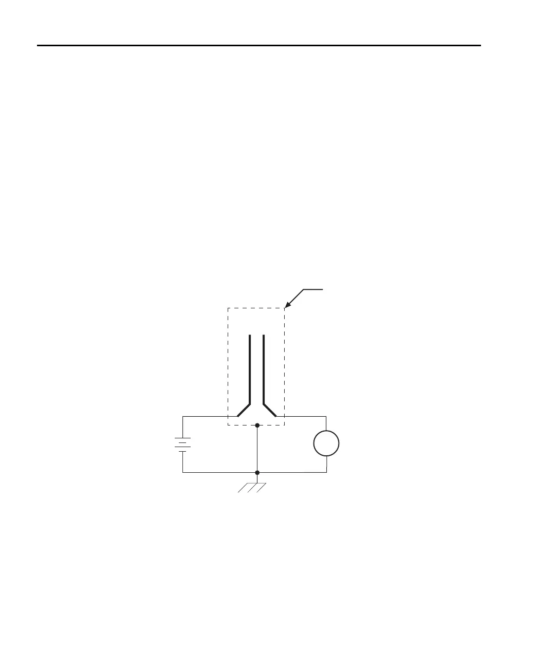
Figure G-18 shows how to measure the insulation resistance between PC board traces.
Note that the drawing shows a “Y” test pattern for the measurement. This is a typical test
pattern for SIR tests.
A bias voltage (typically 50V) is applied to the test pattern for a specified time (typically
one second) to polarize the test pattern. The test voltage (typically 100V) is then applied
and, after a specified time (typically one second), the Model 6487 measures the current.
Surface insulation resistance can now be calculated as follows:
where: V is the sourced test voltage
I is the measured current
Figure G-18
Connections; surface insulation resistance test
A
+
-
HI
LO
HI
LO
PC Board
Test Pattern
6487
V-Source
(V)
6487
Picoammeter
Measured
Current
(I)
Metal
Shield
Equivalent Circuit
 Loading...


