Model 6487 Reference Manual Measurement Concepts and Connections 2-13
Interlock
The Model 6487 has a built-in interlock that works in conjunction with the voltage source.
The interlock prevents the voltage source from being operated on the 50V and 500V
ranges, and optionally on the 10V range, to assure safe operation.
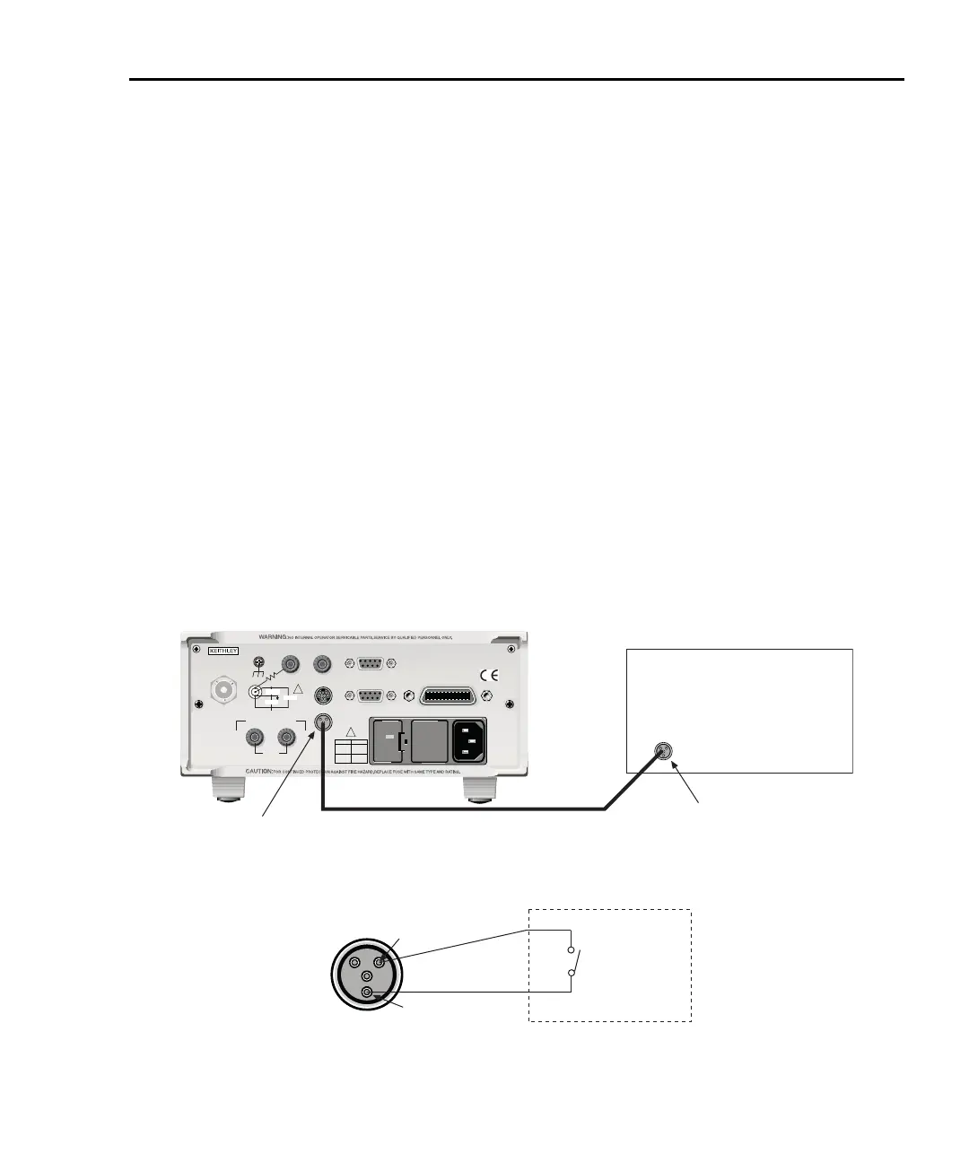
Interlock connections
Figure 2-10 shows interlock connections and the pin diagram of the INTERLOCK
connector. Typically, the INTERLOCK connector is connected to the same type of
connector on the test fixture. A normally open switch is connected to pins 1 and 2 of the
INTERLOCK connector as shown. When the switch is open, the interlock is asserted and
the voltage source cannot be placed in operate on the 50V or 500V voltage source ranges,
and optionally for the 10V range.
t^okfkd If the voltage source is operating when the interlock is asserted, the
voltage source will change to a high impedance state, possibly leaving
charged DUT capacitance.
Figure 2-10
Interlock connections
120
LINE RATING
50, 60Hz
50 VA MAX
INPUT
(CHANGE IEEE ADDRESS
WITH FRONT PANEL MENU)
IEEE-488
CAT I
TRIGGER LINK
RS-232
MADE IN
U. S.A .
ANALOG OUT
DIGITAL I/O
505V
MAX
V-SOURCE OUTPUT
505V PK TO CHASSIS
LO HI
INTERLOCK
INTERLOCK
!
!
FUSE LINE
400mAT
(SB)
100 VAC
120 VAC
200mAT
(SB)
220 VAC
240 VAC
505V PK
505V PK
505V PK
Model 6487
Test Fixture
Interlock
Connector
Interlock
Connector
Interlock
Cable
Pin 1
Pin 2
Test Fixture
Normally
Open
Switch
Interlock Asserted
(Output Inhibited)
with Open Switch
 Loading...


