Model 6487 Reference Manual Limit Tests and Digital I/O 8-7
Component handler interface
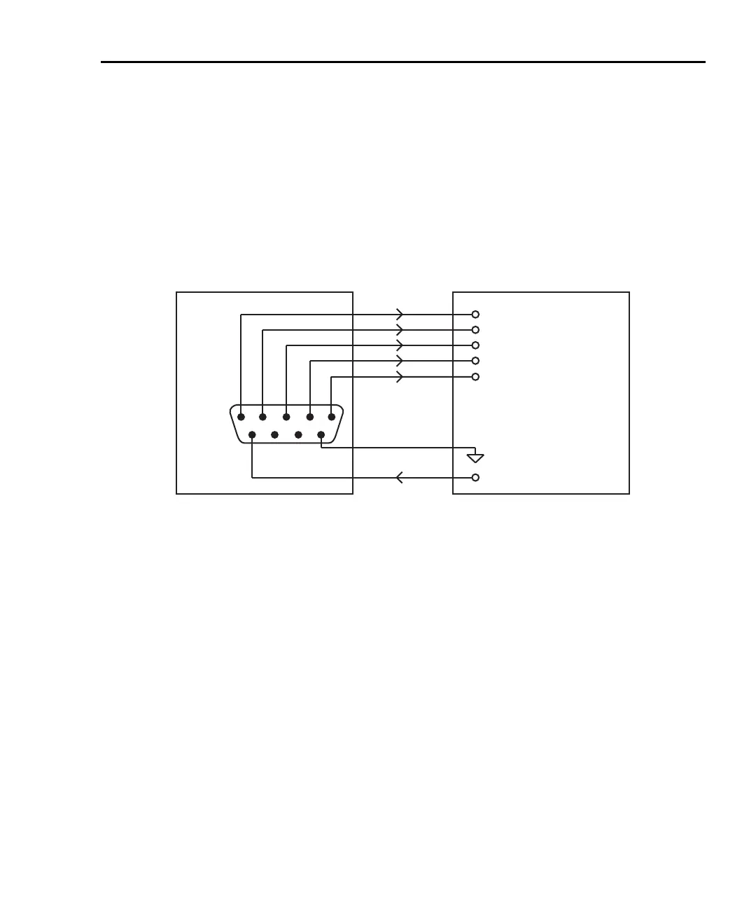
The Model 6487 is interfaced to a component handler via the Digital I/O port as shown in
Figure 8-6. (See “Digital I/O port,” page 8-11 for more information.) The I/O port has four
lines for output signals and one line for input signals. The input line is used to start the test
and the output lines are used to send the test pass/fail signal(s) to the component handler to
perform the binning operation.
Figure 8-6
Handler interface connections
The digital I/O lines are available at the DB-9 connector on the rear panel of the
Model 6487. A custom cable using a standard female DB-9 connector is required for con-
nection to the Model 6487.
Start of test
The SOT (start of test) line of the Digital I/O is used to control the start of the testing pro-
cess. When /STest is the selected arm-in event for the arm layer of the trigger model, the
testing process will start when the SOT line is pulled low. When STest is the selected
arm-in event, the test will start when the SOT line is pulled high. When BSTest is the
selected arm-in event, the test will start when the SOT line is pulled either high or low.
Section 7 provides details on trigger model configuration.
klqb If you do not wish to use the SOT line to start the test, you can use the immediate
arm-in event. The testing process will start as soon as the LIMIT key is pressed
(assuming one or both limit tests are enabled).
The component handler will either maintain the SOT line high or low. This is its “not
ready” condition. When the component handler is ready (DUT properly position in the
handler), it will either pull the SOT line low or high to start the test.
6487
Out 1
Out 2
Out 3
Out 4
Gnd
Dig I/O
1
6
5
9
Input (SOT)
Handler
Line 1
Line 2
Line 3
Line 4 (or EOT)
SOT Strobe Line
Relay Clamp Voltage
V External

 Loading...


