4 Theory of Operation
118 Keysight 34420A Service Guide
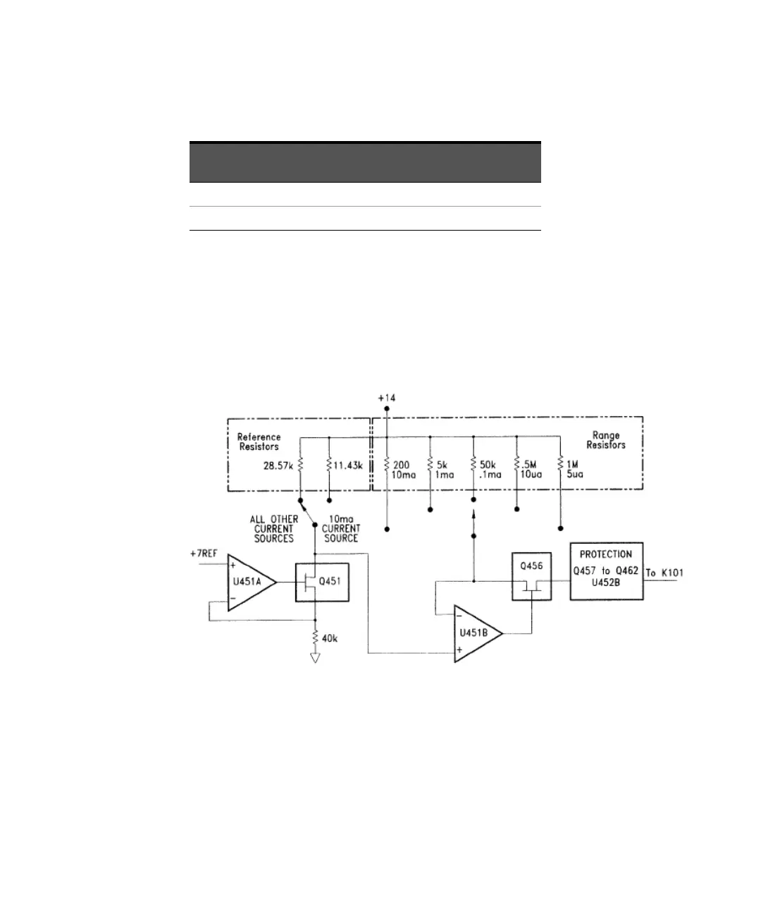
The protection circuits protect the ohms current source from inadvertently applied
voltages up to ± 150 V peak. Protection from large positive voltages is provided by
CR454. Protection from large negative voltages is provided by the sum of the
collector to base breakdown voltages of Q459 and Q461. Bias for these transistors
is provided by Q458 and resistors R461, R464 and R465 when negative over
voltages are applied. U452B also turns off JFET Q456 to protect Q459 and Q461
from excessive temperature rise when negative overvoltages are applied.
When Voltage Limited Resistance measurements are enabled, U310B, U452A and
relay K451 form the output voltage clamp circuit. Voltage clamping is only
available on the 10 Ω and 100 Ω ranges. The ohms output voltage is sensed by
U310B which has a voltage gain of approximately X12. The signal from U310B is
routed by K451 to comparator U452A. If the signal is larger than the “clamp
voltage” set at U452 pin 3, the output ofU452 will go negative, turning on Q457
100 kΩ 10µa 28.57 kΩ 500 kΩ
1 MΩ 5µa 28.57 kΩ 1 MΩ
Table 4-2 2-wire or 4-wire resistance measurements
Ohms range Current
Reference
resistor
Range resistor