Theory of Operation 5
Keysight 34970A/34972A Service Guide 147
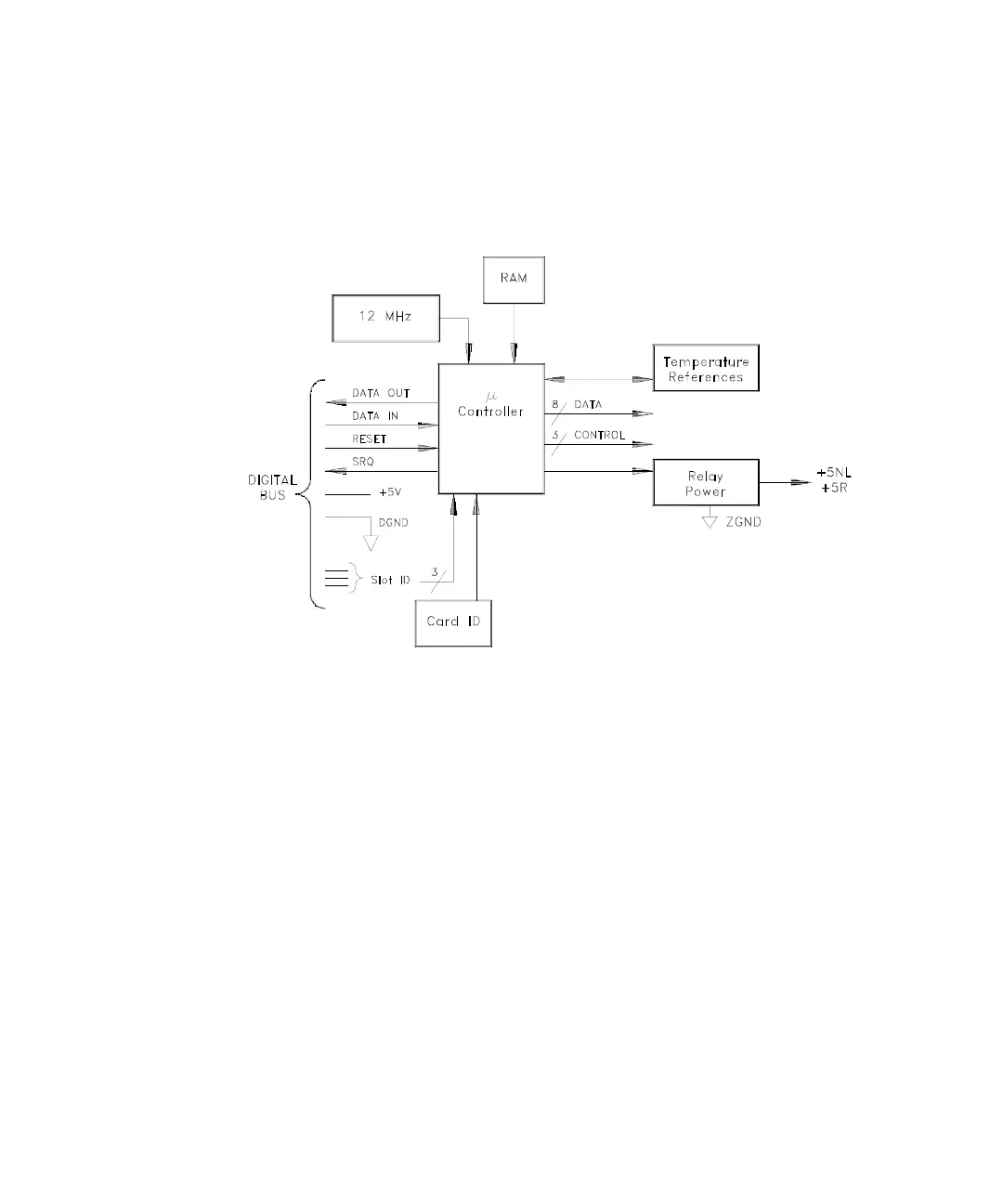
Switch Module Control
A simplified block diagram of a typical module controller is shown below.
In addition to the +5 Volt power supply (Vcc) and ground, the module controller
uses four lines for control and communication:
– RESET, from the Earth Referenced Logic A1U305. RESET is common to all
three slots. The module controller performs a reset when this line goes high.
Reset conditions vary for each plug-in.
– SRQ, to the Earth Referenced Logic A1U305. The SRQ line is a
wired-OR line that can be driven by any plug-in. Consequently, any module
that asserts SRQ (line low), asserts this line in all other slots and at the Earth
Reference Logic.
– DATA IN, from the Floating Logic A1U205 via the opto-isolator A1U312. This
line is connected in common to all three slots.
– DATA OUT, from the module controller to the Floating Logic A1U205 via the
opto-isolator A1U213. This line is a wired-OR line that can be driven by any
module.