5 Theory of Operation
164 Keysight 34970A/34972A Service Guide
Totalizer
Components in this discussion are located on the A1 circuit assembly
(34907-66501).
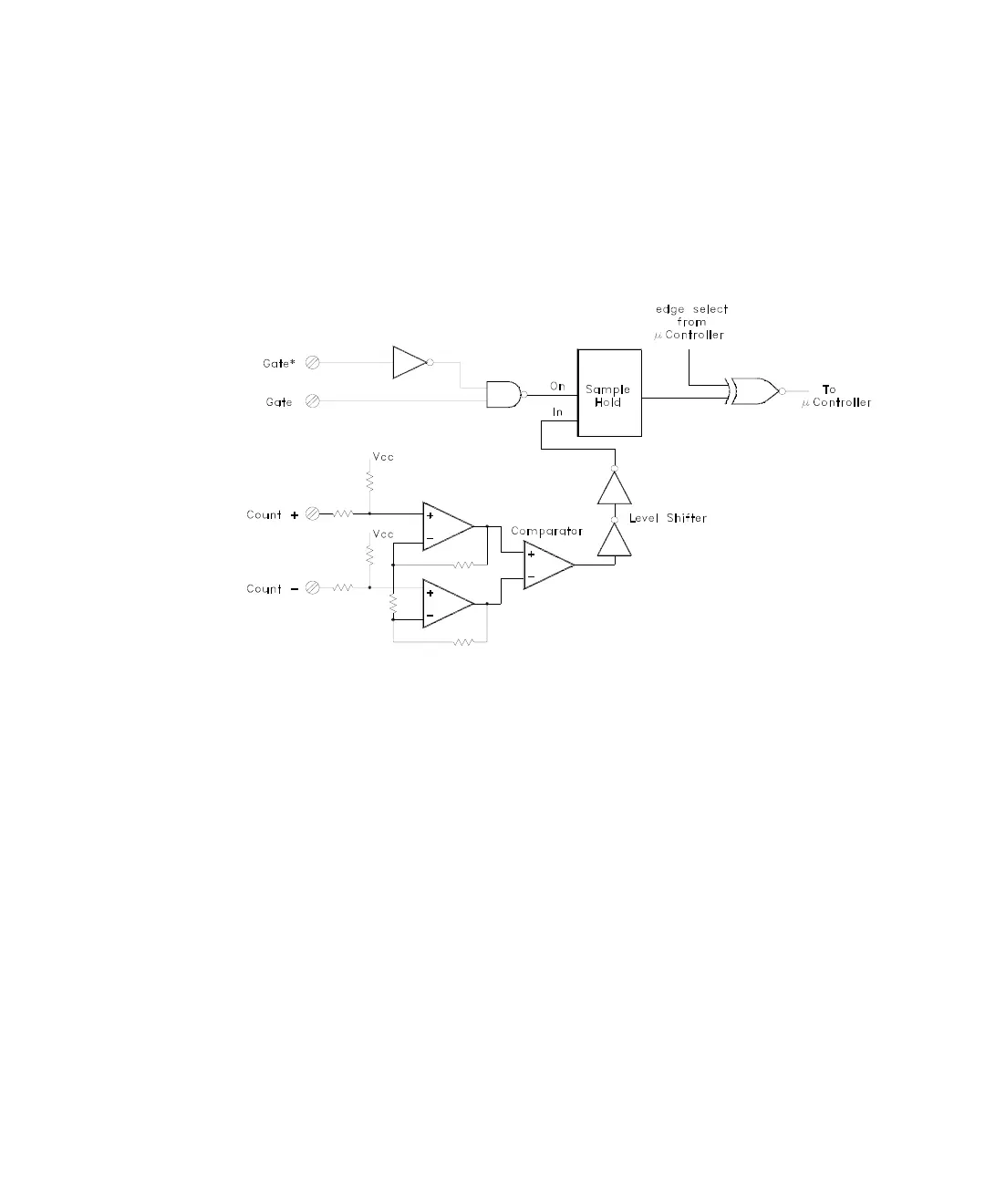
A simplified block diagram of the totalizer input is shown below.
The totalizer counts signals connected to the COUNT+ and COUNT– inputs. Two
op-amps, U108A and U108B, are used for input signal conditioning. Comparator
U109 determines the signal trigger levels based upon the setting of the jumper at
P102. With the P102 jumper in the TTL position, the totalizer counts pulses with
TTL trigger levels. With the jumper at P102 in the AC position the trigger level is at
zero.
The GATE and GATE* input signals control when counting occurs. If no signal is
connected, the totalizer counts any changing signal on the inputs. A TTL low on
the GATE input or a TTL high on GATE* input will halt counting.
Count edge selection is controlled from a U101 port bit (P0.6) through the
exclusive OR gate U111. When the P0.6 signal is low, the count increments on the
rising edge of the input signal. When the P0.6 signal is high, the count increments
on the falling edge of the input signal.

 Loading...

