4 Calibration Procedures
120 Keysight 34970A/34972A Service Guide
Before executing each test, you must press to enable reading monitoring on
the selected channel (or use the ROUTe:MON command from the remote interface).
6 Subtract the thermocouple error from the displayed temperature. Verify the
result is within ± 1.0 °C of the known temperature (set in step 4).
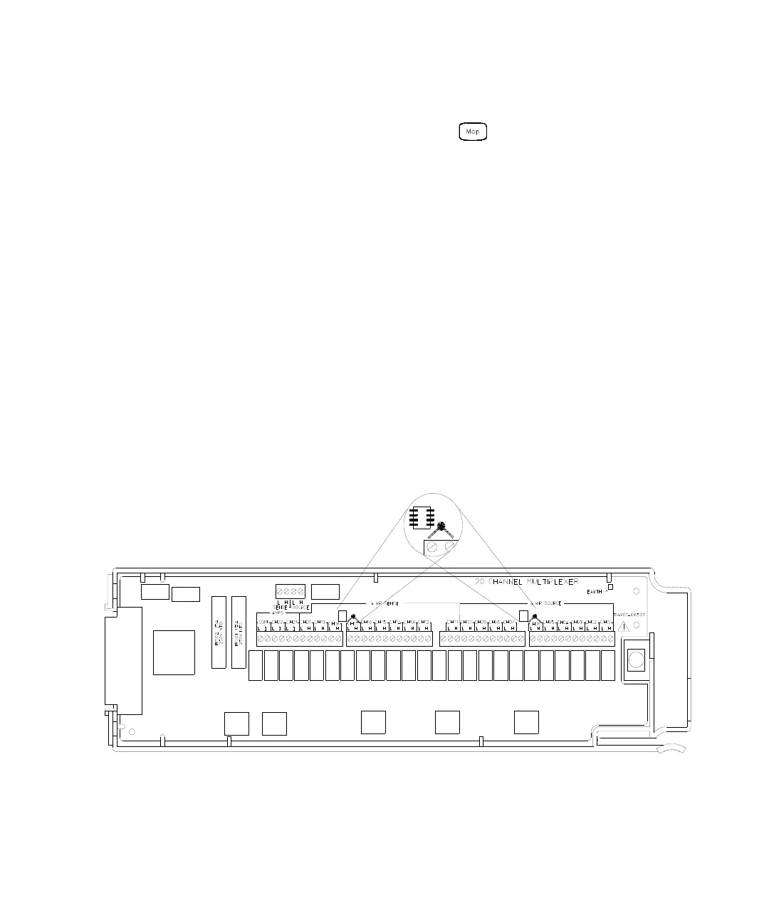
Thermocouple Reference Junction Adjustments
These adjustments are plug-in module specific and only affect thermocouple
measurements. The calibration constants created by these adjustments are stored
in non-volatile memory on the plug-in module.
1 Connect a 10 kW (YSI 44031) thermistor to each of the following channels (a kit
of five thermistors is available as Keysight part number 34308A):
For the 34901A Channels 6 and 17
For the 34902A Channels 6 and 11
For the 34908A Channels 6 and 16
Keep the thermistor leads as short as possible. Locate the thermistor as near
to the input connectors as possible.

 Loading...

