Keysight 34970A/34972A Service Guide 17
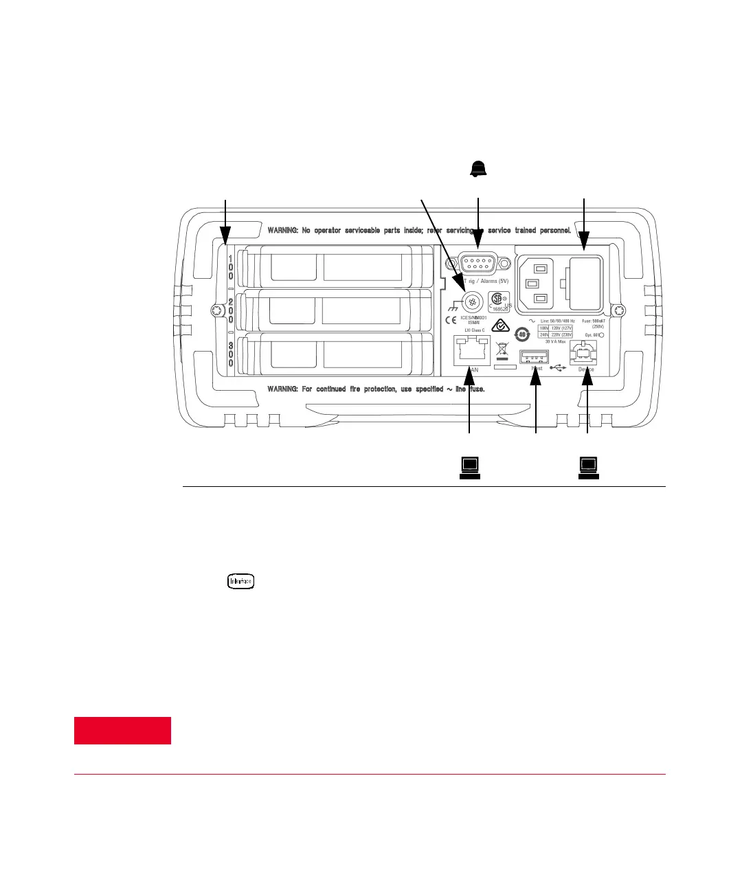
The 34972A Rear Panel at a Glance
1 Slot Identifier (100,200, 300)
2 Chassis Ground Screw
3 Ext Trig Input / Alarm Outputs / Channel
Advance Input / Channel Closed Output
4 Power-Line Fuse-Holder Assembly
5 LAN Connector
6 USB Drive Connector
7 USB Interface Connector
[a]
[a] Under some conditions, while using the USB interface with the 34972A, you may experience connection or data
loss in the presence of an electrical transient from the main power line. You can re-establish the USB
communication by performing a reboot (cycle power) on the instrument. You can make the USB connection less
susceptible to a potential power line transient by inserting a USB hub in the connection between the computer and
the instrument.
Use the Menu to:
– Select and configure the LAN and USB interfaces (see Chapter 2).
For protection from electrical shock, the power cord ground must not be
defeated. If only a two-contact electrical outlet is available, connect the
instrument’s chassis ground screw (see above) to a good earth ground.