Theory of Operation 5
Keysight 34970A/34972A Service Guide 165
Analog Output
Components in this discussion are located on the A1 circuit assembly
(34907-66501).
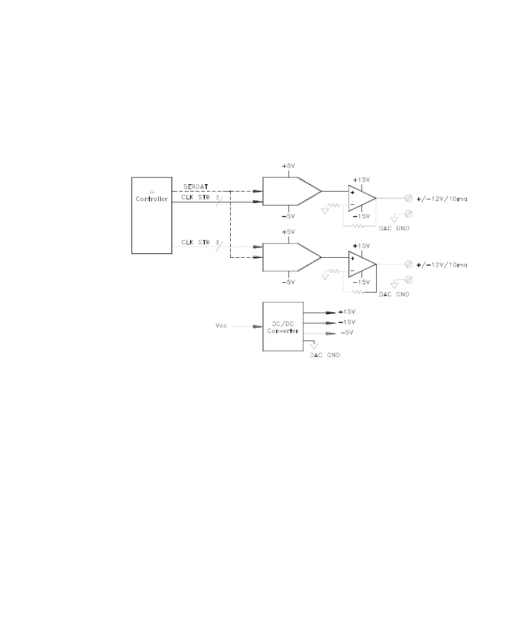
A simplified block diagram of the analog output channels is shown below.
Communication with each DAC (U503 and U504) is via three lines: SERSTB,
DACCLK, and SERDAT. Each DAC has a voltage output of ±3 V. U505 and U506
amplify this voltage to the ±12V output.
A DC/DC converter is used to provide the ± 15V supplies to U505 and U506. The ±
15V supplies also are used at the input of the totalizer. U502 provides the –5 V
supply used by the DACs.
A line from U101 P0.4 is used to control the output of U510. After a reset or
power-up, U510 is held in the shutdown state. U101 turns on the DC/DC
converter in response to commands from the main controller. The main controller
paces the turn on of the DC/DC converters to ensure that if multiple modules are
installed, the backplane power supply is not pulled down by the in-rush current of
the DC/DC converters.

 Loading...

