Home
Keysight Technologies
Switch
34972A
Keysight Technologies 34972A Service Guide
5
of 1
of 1 rating
197 pages
Give review
Manual
Specs
To Next Page
To Next Page
To Previous Page
To Previous Page
Loading...
5
Theory of Operation
158
Keysight 34970A/34972A Service Guide
34905A/34906A
Components in this d
iscussion are located on the A1 cir
cuit assembly
(34905-66501 or 34906-66501).
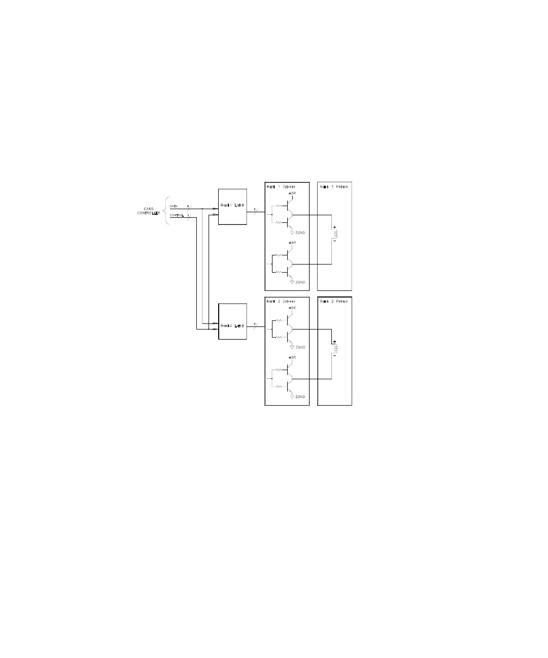
The contr
ol cir
cuitry has of two grouping
of buffers, r
elay drivers and r
elays, one
for each mul
tiplexer bank.
157
159
Table of Contents
Copyright Notice
2
Declaration of Conformity
2
Safety Information
2
Technology Licenses
2
Software Updates/Licenses
3
Safety Symbols
4
General
5
Before Applying Power
5
Ground the Instrument
5
Do Not Operate in an Explosive Atmosphere
5
Do Not Remove the Instrument Cover
6
Do Not Modify the Instrument
6
In Case of Damage
6
Safety Considerations
5
Environmental Conditions
7
Regulatory Markings
8
Sales and Technical Support
9
Waste Electrical and Electronic Equipment (WEEE) Directive
9
Product Category
9
The Front Panel at a Glance
11
The Front-Panel Menu at a Glance
12
Display Annunciators
14
The 34970A Rear Panel at a Glance
16
The 34972A Rear Panel at a Glance
17
The Plug-In Modules at a Glance
18
A Multifunction Module
20
In this Book
21
Table of Contents
23
Specifications
29
1 Specifications
30
Quick Start
32
To Prepare the Instrument for Use
33
Quick Start
33
To Connect Wiring to a Module
34
To Set the Time and Date
36
To Configure a Measurement Channel
37
To Monitor a Single Channel
38
To Close a Channel
39
If the Instrument Does Not Turn on
41
To Adjust the Carrying Handle
43
To Rack Mount the Instrument
44
Front-Panel Overview
48
Front-Panel Menu Reference
49
Front-Panel Overview
49
To Unsecure for Calibration
52
To Secure against Calibration
53
To Change the Security Code
54
Error Messages
55
To Perform a Zero Adjustment
56
To Apply MX+B Scaling to Measurements
57
To Read the Relay Cycle Count
58
To Read a Digital Input Port
59
To Write to a Digital Output Port
60
To Read the Totalizer Count
61
To Output a DC Voltage
62
Calibration Procedures
64
Keysight Technologies Calibration Services
66
Calibration Interval
66
Adjustment Is Recommended
66
Time Required for Calibration
67
Automating Calibration Procedures
67
Recommended Test Equipment
68
Input Connections
69
Calibration Security
71
To Unsecure the Instrument Without the Security Code
72
Calibration Message
74
Calibration Count
74
Calibration Procedure
75
Aborting a Calibration in Progress
75
Test Considerations
76
Performance Verification Tests
77
Self-Test
78
Quick Performance Check
79
Performance Verification Tests
79
Internal DMM Verification Tests
80
Zero Offset Verification
80
Gain Verification
82
Optional AC Performance Verification Tests
87
Internal DMM Adjustments
88
Zero Adjustment
88
Gain Adjustment
89
VDC Adjustment Procedure (Optional)
92
Plug-In Module Test Considerations
94
Relay Verification
95
Relay Cycle Count
95
(Optional) 34901A Relay Contact Resistance Verification
96
(Optional) 34902A Relay Contact Resistance Verification
103
(Optional) 34903A Relay Contact Resistance Verification
108
(Optional) 34904A Relay Contact Resistance Verification
109
(Optional) 34905/06A Relay Contact Resistance Verification
112
(Optional) 34908A Relay Contact Resistance Verification
113
Thermocouple Reference Junction (Optional)
119
Thermocouple Reference Junction Verification
119
Thermocouple Reference Junction Adjustments
120
34907A Analog Output
122
Analog Output Verification Test
122
Analog Output Adjustment
123
5 Theory of Operation
125
Theory of Operation Theory of Operation
126
System Block Diagram
127
Floating Logic
128
Memory
131
Earth-Referenced Logic
132
Power Supplies
133
Front Panel
135
Backplane
136
Analog Bus
136
Digital Bus
136
Internal DMM
137
DMM Block Diagram
137
Input
138
Input Amplifier
139
Ohms Current Source
141
AC Circuit
142
A-To-D Converter
144
Switch Modules
146
Switch Module Control
147
Relay Drivers
149
34901A
151
34902A
153
34903A
155
34904A
156
34905A/34906A
158
34908A
160
Multifunction Module
162
Multifunction Control
162
Totalizer
164
Analog Output
165
Digital I/O
166
Service
169
Service
170
Service Service
170
Operating Checklist
171
Types of Service Available
172
Cleaning
173
Repackaging for Shipment
173
Electrostatic Discharge (ESD) Precautions
174
Surface Mount Repair
174
To Replace the Power-Line Fuse
175
Troubleshooting Hints
175
Self-Test Procedures
179
Disassembly
184
General Disassembly
185
Internal DMM Disassembly
186
Front Panel Disassembly
187
Additional Chassis Disassembly
188
Plug-In Module Disassembly
189
Recyclable Parts
191
Replaceable Parts
194
To Order Replaceable Parts
194
Parts List for 34970A/34972A and 34901A
194
Other manuals for Keysight Technologies 34972A
Manual
9 pages
5
Based on 1 rating
Ask a question
Give review
Questions and Answers:
Need help?
Do you have a question about the Keysight Technologies 34972A and is the answer not in the manual?
Ask a question
Keysight Technologies 34972A Specifications
General
Brand
Keysight Technologies
Model
34972A
Category
Switch
Language
English
Related product manuals
Keysight Technologies 34970A
197 pages
Keysight Technologies E4360A
118 pages