Installation and Service Guide N5250-90001 3-21
PNA Series Microwave Network Analyzer System System Installation
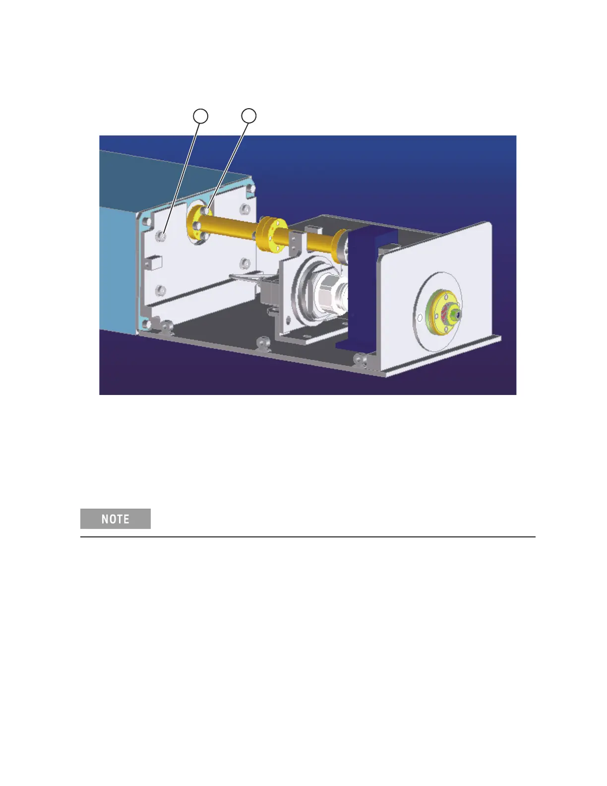
N5250A Disconnecting the Combiner Assembly From the mm-Wave Module
Figure 3-12 New Design Combine
r Assembly and mm-Wave Module: View 3
4. Remo
ve the four waveguide screws (item 1).
5. Remove the four screws (item 2).
6. Reverse the process to reassemble.
Do NOT switch modules. Combiner must be reassemb
led to the mm-wave
module in which it was originally installed.
7. Perfo
rm an Operator’s Check after reassembly to test for power holes, etc.
(4 places)
2
1
(4 places)
N5230_013_318
 Loading...


