24
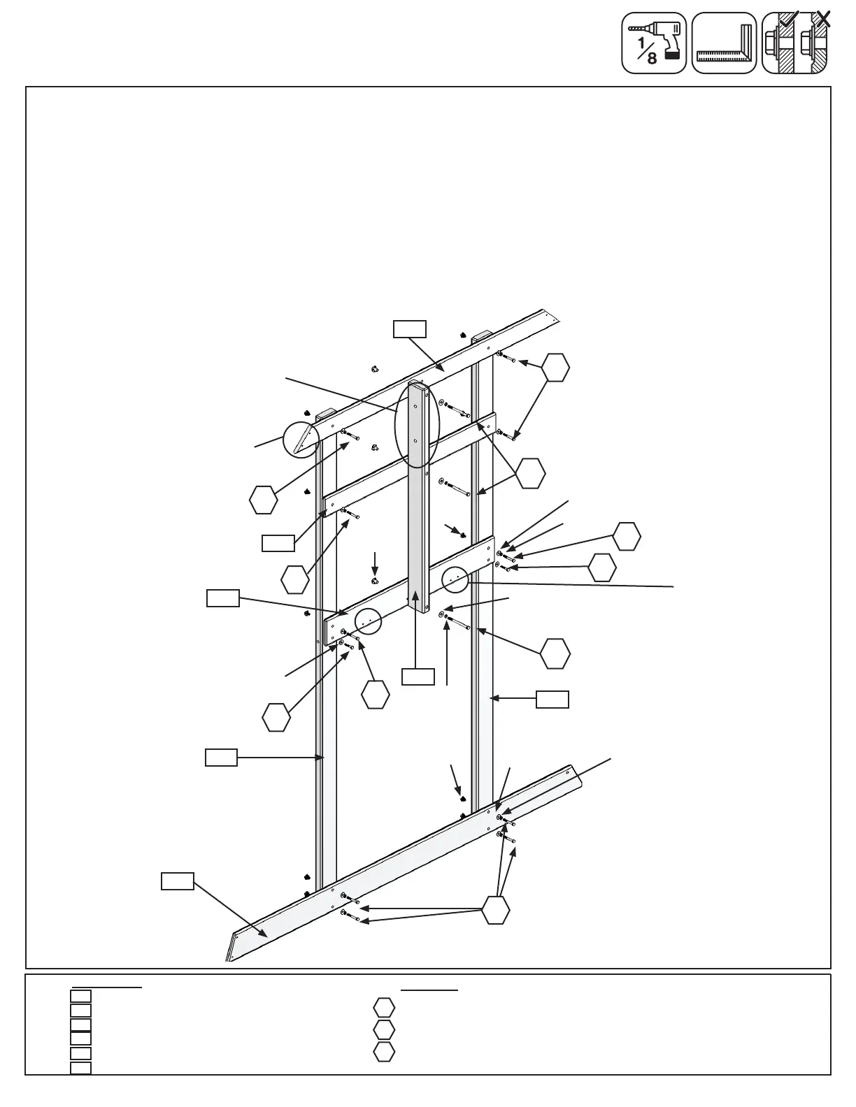
Step 8: Swing Wall Assembly
Wood Parts
Hardware
10 x 1/4 x 2” Hex Bolt (1/4” lock washer, 1/4” at washer, 1/4” t-nut)
3 x 5/16 x 4” Hex Bolt (5/16” lock washer, 5/16” at washer, 5/16” t-nut)
2 x 1/4 x 1-1/2” Lag Screw (1/4” at washer)
1 x Floor End 1 x 5 x 35-1/4”
1 x Side Roof 1 x 4 x 55-1/8”
2 x Post 2 x 4 x 84-3/8”
1 x Wall Mount 2 x 4 x 38-1/4”
1 x SW Ground 1 x 5 x 74”
1 x SW Side 1 x 4 x 35-7/8”
2211
2228
2215
1935
LS1
H2
G4
Fig. 8.1
2215
2223
1935
H2
H2
A: Loosely attach (2223) SW Ground using 4 (H2) 1/4 x 2” Hex Bolts (with lock washer, at washer and t-nut);
(2211) Floor End (in the top holes); (2224) SW Side and (1935) Side Roof using 2 (H2) 1/4 x 2” Hex Bolts (with
lock washer, at washer and t-nut) for each board to 2 (2215) Posts. (g. 8.1) Note: Keep all bolts loose.
B: Place (2228) Wall Mount across (2211) Floor End, (2224) SW Side and (1935) Side Roof then attach using 3
(G4) 5/16 x 4” Hex Bolts (with lock washer, at washer and t-nut) as shown in g. 8.1. Notice the side holes are
towards the top of the board.
Note: Pre-drill all holes using a 1/8” drill bit before installing the lag screws.
C: Make sure assembly is square and then fasten (2211) Floor End to (2215) Posts using 2 (LS1) 1/4 x 1-1/2”
Lag Screws (with at washer). (g. 8.1) Tighten all (H2) 1/4 x 2” Hex Bolts.
2228
2215
2211
H2
LS1
H2
G4
G4
H2
1/4” at
washer
Notice the hole
locations in (2228)
Wall Mount
2223
5/16” at
washer
1/4” lock
washer
1/4” at
washer
1/4”
t-nut
LS1
Notice the pilot hole
locations towards
bottom of board
2224
Notice shorter end on
this side and angle
facing up.
2224
5/16”
t-nut
H2
5/16” lock
washer
1/4” at
washer
1/4” lock
washer
1/4”
t-nut
 Loading...