32
Wood Parts Hardware
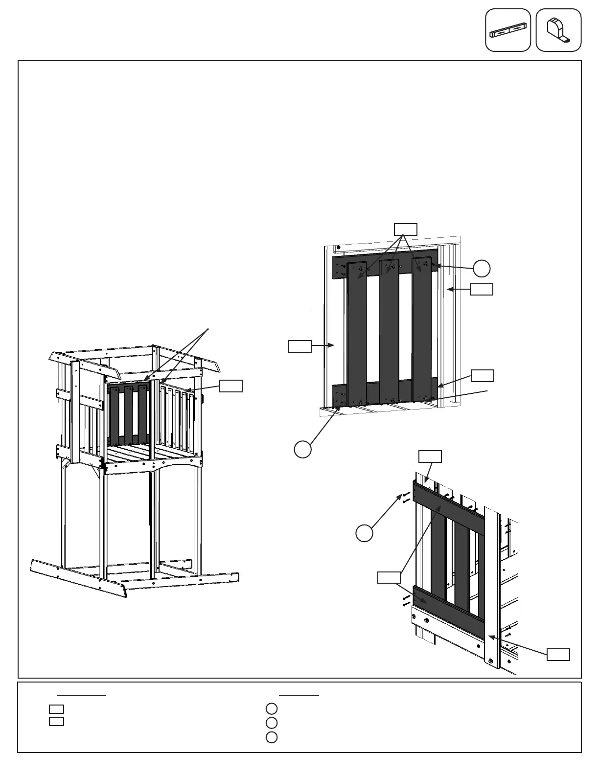
Fig. 16.2
12 x #8 x 7/8” Truss Screw
4 x #8 x 1-1/8” Wood Screw
4 x #8 x 1-1/2” Wood Screw
3 x Wall Board 1/2 x 4 x 22”
2 x CE Wall Board 1 x 4 x 20”
2227
S0
Step 16: Back Wall Assembly
A: On the Back Wall, tight to the oor boards, attach 1 (1227) CE Wall Board to the outside of (2215) Post on
Cafe Wall side with 2 (S2) #8 x 1-1/2” Wood Screws and to the inside face of (2200) Back Divider with 2 (S1) #8 x
1-1/8” Wood Screws. (g. 16.1, 16.2 and 16.3)
B: Flush to the top of (2203) Cafe Side Top, making sure board is level, attach 1 (1227) CE Wall Board to the
outside of (2215) Post on Cafe Wall side with 2 (S2) #8 x 1-1/2” Wood Screws and to the inside face of (2200)
Back Divider with 2 (S1) #8 x 1-1/8” Wood Screws. (g. 16.1, 16.2 and 16.3)
C: In between (2215) Post and (2200) Back Divider evenly space and attach 3 (2227) Wall Boards to both (1227)
CE Wall Boards using 4 (S0) #8 x 7/8” Truss Screws per board. Make sure the bottom of the boards are tight
against the oor boards. The distance between boards should not exceed 3-1/4” (g. 16.1, 16.2 and 16.3)
2203
2200
1227
2215
Fig. 16.1
x 4 per board
1227
S1
S2
Fig. 16.3
Back Wall
Outside View
2227
Inside View
Top of CE Wall Board
ush to Cafe Side Top
x 2 per board
S0
S1
Tight to oor boards
2200
1227
2215
x 2 per board
S2
Cafe Wall