26
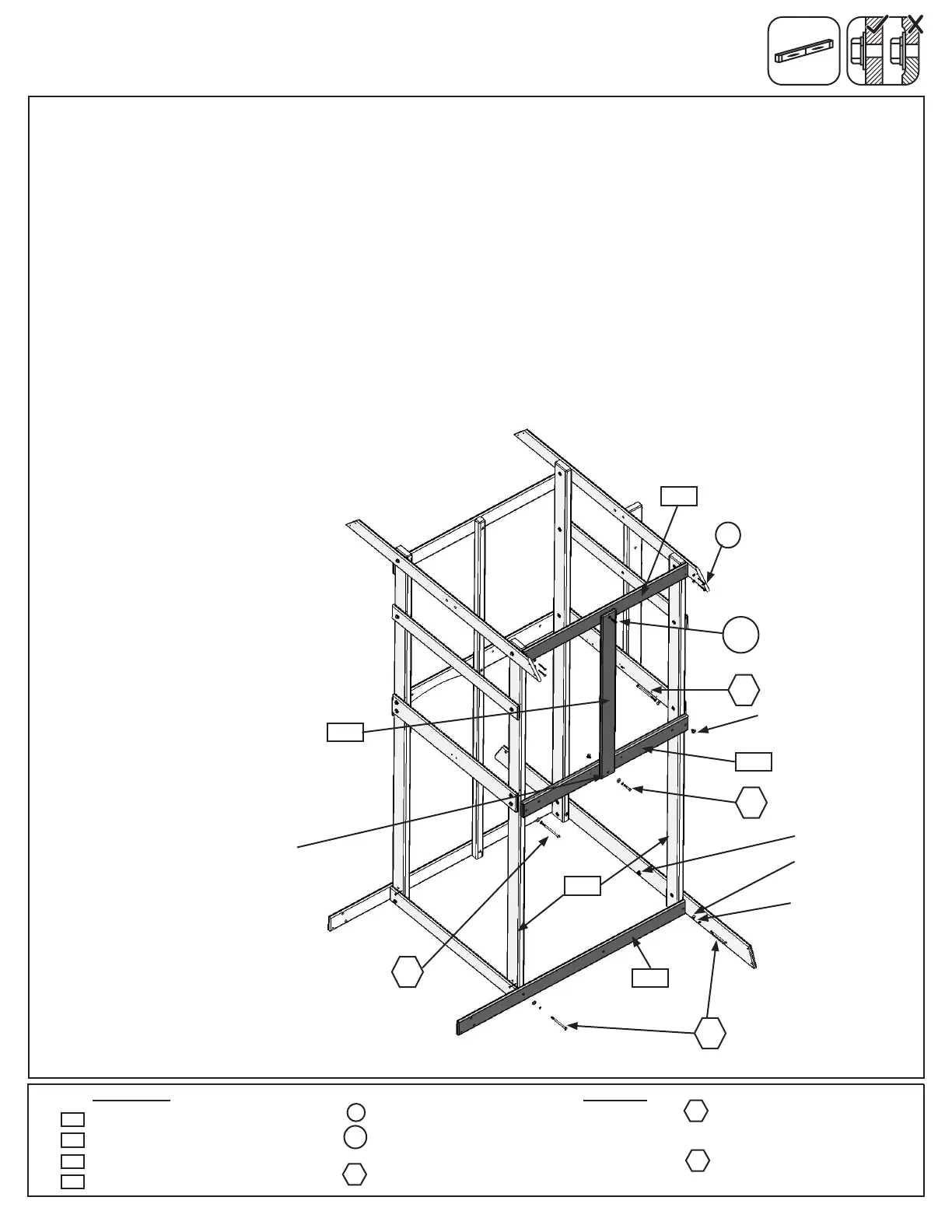
Step 10: Back Frame Assembly
A: On the opposite side of the assembly loosely attach (2210) Front Back Ground to the (2215) Posts with 2
(H4) 1/4 x 4” Hex Bolts (with lock washer, at washer and t-nut). (g. 10.1)
B: Loosely attach (1894) Back Floor to both (2215) Posts using 2 (H5) 1/4 x 4-1/2” Hex Bolts (with lock washer,
at washer and t-nut). The bolt on the Swing Wall side must be installed from inside the fort. Notice the middle
bolt hole is towards the bottom of the board. (g. 10.1)
C: Attach (2200) Back Divider to (1894) Back Floor with 1 (H1) 1/4 x 1-1/2” Hex Bolt (with lock washer, at
washer and t-nut) and to (1906) Top Front Back with 1 (PB2) 1/4 x 1-1/4” Pan Bolt (with lock washer, at washer
and t-nut). (g. 10.1)
D: Make sure (1906) Top Front Back is level then attach to both (2215) Posts using 4 (S7) #12 x 2” Pan Screws
(with 3/16” at washers). (g. 10.1)
E: Tighten all bolts.
Wood Parts Hardware
Fig. 10.1
4 x #12 x 2” Pan Screw (3/16” at washer)
1 x 1/4 x 1-1/4” Pan Bolt
(1/4” lock washer, 1/4” at washer, 1/4” t-nut)
1 x 1/4 x 1-1/2” Hex Bolt
(1/4” lock washer, 1/4” at washer, 1/4” t-nut)
S7
PB2
1894
2210
1906
Swing Wall
H5
H5
2215
1 x Front Back Ground 1 x 4 x 53”
1 x Back Floor 5/4 x 4 x 38-1/2”
1 x Back Divider 1 x 4 x 39-3/16”
1 x Top Front Back 1 x 4 x 38-1/2”
2210
1894
2200
1906
H4
2 x 1/4 x 4” Hex Bolt
(1/4” lock washer, 1/4” at washer,
1/4” t-nut)
2 x 1/4 x 4-1/2” Hex Bolt
(1/4” lock washer, 1/4” at washer,
1/4” t-nut)
H1
H1
PB2
H5
H4
2200
S7
with 3/16”
at washer
1/4” lock
washer
1/4” at
washer
1/4”
t-nut
x 4
1/4”
t-nut
Notice hole towards
bottom of board