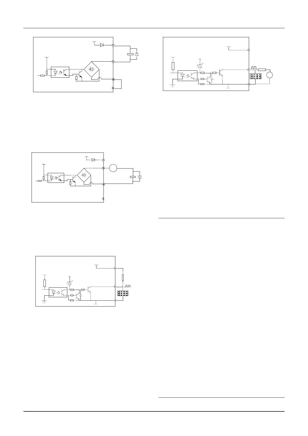
Fig 4-13 Wiriing method 1 of multi-function
output terminal
2. Multi-function output terminal Y1, Y2 can use the
external 24 power supply too, the wiring is as shown in
Fig.4-14.
Fig 4-14 Wiriing method 2 of multi-function output
terminal
3. Y2 is also can be used as pulse output. If Y2 uses the
internal 24v power supply. The wiring is shown in
Fig.4-15.
Fig 4-15 Wiring method 1 of output terminal Y2
4. When Y2 is used as a pulse output, it also can use the
external power supply. The wiring is shown in Fig.4-16
Fig.4-16 Wiring method 2 of output terminal Y2
Wiring of relay output terminals R1a, R1b and R1c
If the drive drives an inductive load (such as
electromagnetic relays and contactor), then a surge
suppressing circuit should be added, such as RC
snubbing circuit (Notice that the leakage current must be
smaller than the holding current of the controlled relay
or contactor) and varistor or a free-wheeling diode (Used
in the DC electric-magnetic circuit and pay attention to
the polarity when installing). Snubbing components
should be as close to the coils of relay or contactor as
possible.
Note
1. Don’t short circuit terminals 24V and COM,
otherwise the control board may be damaged.
2. Please use multi-core shielded cable or multi-stranded
cable(above 1mm) to connect the control terminals.3.
When using a shielded cable, the shielded layer’s end
that is nearer to the drive should be connected to PE.
4. The control cables should be as far away(at least
20cm) from the main circuits and high voltage cables as
possible (including power supply cables, motor cables,
relay cables and contactor cables and so on). The cables
should be vertical to each other to reduce the disturbance
to minimum.
5. The resistors R in Fig. 4-13 and Fig.4-14 should be
removed for 24V input relays, and the resistance of R
should be selected according the parameters of relay for
non-24V relay.
6. Digital output terminal can not stand the voltage
higher than 30V
 Loading...