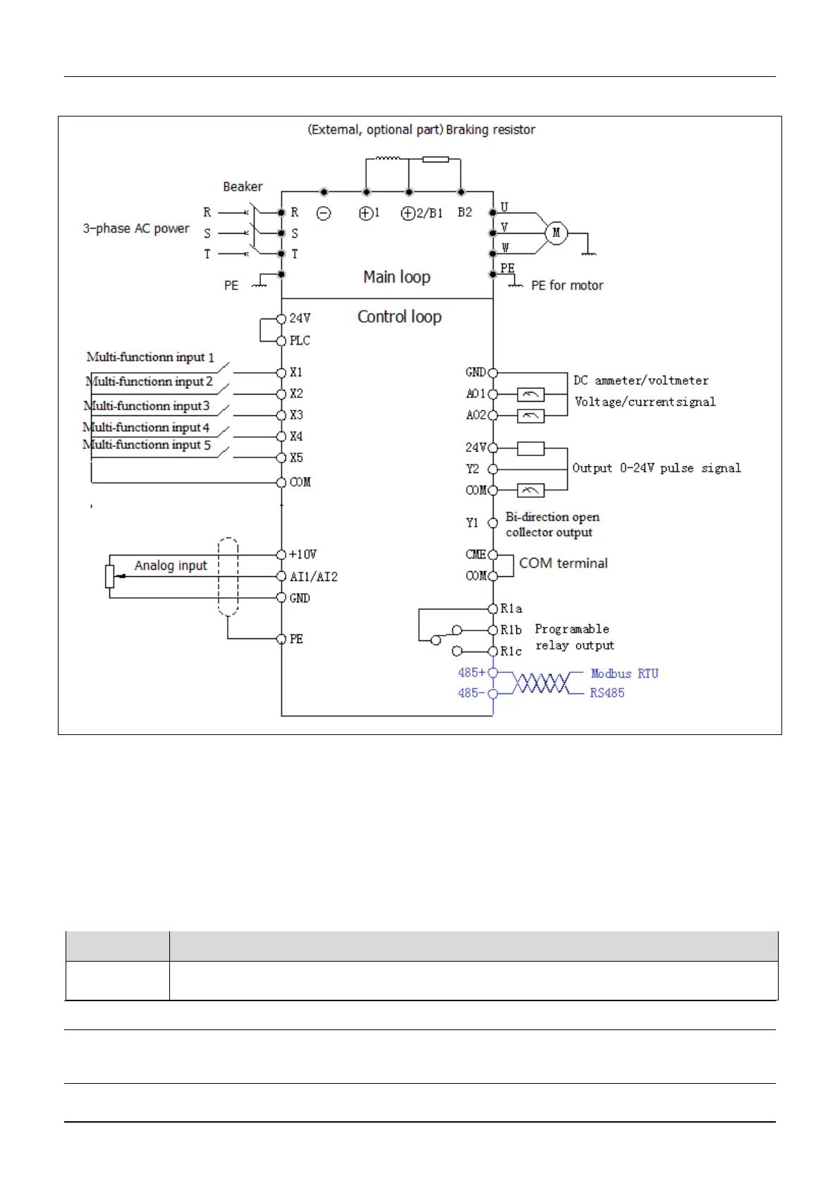
Fig.4-1 Basic wiring chart(Only the model with L support RS485)
4.2 Wiring and configuration of control circuit
4.2.1 Wiring of control circuit termial.
Wire the terminals correctly before using the Drive. Refer to the table 4-2 for control circuit terminal function
Table 4-2 Control circuit terminal function
Analog input and output terminal, RS232 and RSRS485 communication port
Note
It is recommended to use cables bigger than 1mm2 to connect to the terminals.
Arrangement of control circuit terminals is as follows
 Loading...